1048
Proceedings of the 18
th
International Conference on Soil Mechanics and Geotechnical Engineering, Paris 2013
wall positions. The PFC
2D
uses simple fluid coupling scheme
(Patankar, 1980) for incompressible viscous or inviscid flow on
a fixed rectangular grid aligned with and superimposed on the
Cartesian axes for the DEM model. The fluid flow in the PFC
2D
uses the numerical scheme of the Navier-Stokes’ equations. The
effects of solids on fluid motion are introduced to the numerical
scheme of the Navier–Stokes’s equations in terms of porosity
and coupling force averaged over each element (Bouillard et al.,
1989). Fluid-solids coupling time-step is 100 times larger than
individual particles collision time-step. The drag force applied
by all the particles in each fluid element to the fluid is defined
as:
b
f
U
(2)
where
b
f
=drag force applied to the unit volume of fluid,
=coefficient for flow,
U
=average relative velocity between the
particles and the fluid, defined as:
(3)
where
u
=average velocity of all particles in a given fluid
element,
v
=fluid velocity. Different expressions for coefficient
are given for porosities with values higher and lower than
e
=0.8 (Bouillard et al. 1989):
2 2
(1 ) (150(1 ) 1.75
);
0.8
f
e
e
d U e
d e
(4)
1.7
(1 )
4
;
0.8
3
f
d
U e
C
e
de
(5)
0.687
24(1 0.15Re )
;Re 1000
Re
0.44;Re 1000
p
p
p
d
p
C
(6)
Re
f
p
U ed
(7)
where
d
=average diameter of the particles occurring in the
element,
C
d
=turbulent drag coefficient defined in terms of
particle Reynolds number
Re
p
,
e
=porosity,
f
=fluid density,
=fluid dynamic viscosity. A fluid force equal and opposite acts
to the particles in each fluid element. The fluid drag force
applied to individual discrete particles is:
(8)
where
drag
f
=fluid drag force on the particle and
r
=particle
radius. The fluid-applied force acts at the particle center of
mass, and the rotational moment is not applied to the particle.
The resultant force that determines the individual particle
motion is the sum of the averaged fluid drag and individual
particle-particle or particle-wall collision forces and moments.
2.1.1 User defined lubrication contact model
The particle contact model in PFC2
D
is built to model the
elasto-hydrodynamic deformation of a solid elastic sphere that
is immersed in a viscous fluid and in close motion toward
another sphere or a wall. The model is based on the criteria for
predicting whether two solid particles will stick or rebound
subsequent to impact immersed in the fluid.
The lubrication force,
F(t)
act as contact force when two
spheres are approaching each other (Davis et al., 1986):
(9)
where
=fluid dynamic viscosity,
a
=particle radius,
v
=relative
approaching velocity of two particles and
x
=distance between
particle surfaces. Physically, the lubrication of a contact can be
viewed as a thin layer of viscous fluid that acts as a cushion
between two particle surfaces. It slows down the initial particles
velocities and decreases the kinetic energy of the particles. If
the balance of the lubrication force and the fluid approaching
velocities causes adjacent particles slowing down to near zero,
the
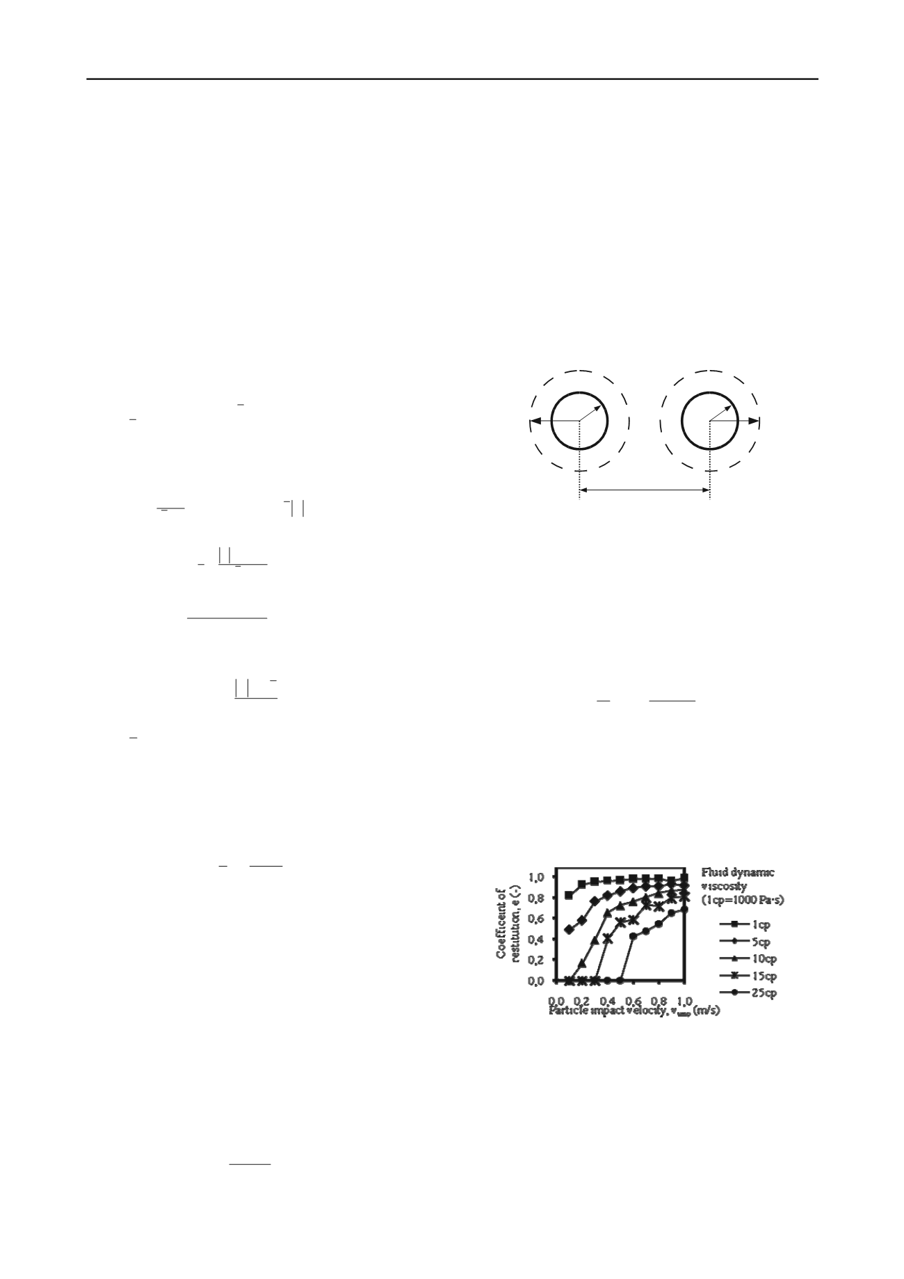
he active particle radius is represented in DEM by the apparent
radius that is bigger than the particle we want to model (Fig. 2).
particles may stick next to each other and get trapped with
the fluid and agglomerate.
The elastic rebound depends on the overlap of two particles
if they are in contact with the real radii (
r
ij
<r
c
) and the
lubrication damping force acts upon contact when it is activated.
T
RT
(
j
)
rij
RT
(
i
)
RI
(
j
)
RI
(
i
)
U u
v
Fig
on are activated. The
contact force logic can be written for PFC
2D
for the user defined
nd compiled in C++ as:
if
r
ij
≥ 2
r
c
=
crit
(10)
if
r
< 2
r
c
=
crit
(11)
r
c
=real particle radius,
=fluid
ynamic viscosity,
k
is the spring stiffness,
c
=dashpot constant,
and
lub
=lubrication constant.
ure 2. Schematic of the apparent (RI) and real (RT) radii and the
approaching distance,
r
ij
.
The apparent radius enables the activation of the contact and
calling the contact force when the particles approach each other
at a close distance. During the time-stepping procedure, if the
particles are close enough that they overlap with their real radii,
then the elastic rebound and the fricti
contact model, a
2
6
lub
( 2 )
ij
ij
ij
ij
c
v
v
F ma
a
ij
where
F
c
=contact force,
d
ij
=overlap of the particles,
r
ij
=distance
between the particles centers,
d
Figure 3. Particle drop test results for the sand particle with diameter
d=0.25mm using user-defined lubrication force contact model
The coefficient of restitution of this system is non-linear
curve dependent on the approaching velocity. Particle-particle
interactions are governed by the user-defined contact model,
and for the purpose of calculating their motion effect of fluid
motion in fluid-solids coupled scheme they are averaged in each
fluid cell (Eqn. 3). Fig. 3 shows the result of restitution
coefficient simulation in PFC
2D
using the developed user
defined contact model for collision between sand particle and
wall. Coefficient of restitution is the ratio between velocity after
c
x
r r
(2 )
c
c
ij
ij
F ma k r r cv
3
4
3 (1
b
drag
f
f
r
e
)
2
6 ( )
a v
F t
x


