3445
Technical Committee CFMS /
Comité technique CFMS
The uncertainties in E
Si
can be analyzed by attributing values
to E
Si
variance (V[E
Si
]), or by analyzing the sources of
uncertainties in the E
Si
estimations. Considering that the moduli
E
Si
are estimated from CPT, three sources of uncertainty are
suggested to be accounted for:
(i) The uncertainties due to field measurements (q
ci
, in this
case) – in other words, the sum of inherent soil variability and
equipments/measurement procedures errors of CPT. This
variance is named V
1
[E
Si
].
(ii) The uncertainties due to transformation models – in other
words, the empirical correlations used to transform the field
measurement results (q
ci
) into required design parameters (E
Si
).
This variance is named V
2
[E
Si
];
(iii) Statistical uncertainties – due to limited sampling or
insufficient representative sampling data in the field. This
variance is named V
3
[E
Si
].
The sources of uncertainties represented by V
1
[E
Si
] and
V
2
[E
Si
] are explicit in the E
Si
x q
ci
correlations. The typical form
of those correlations is:
)
] [ .
] [
2
1
Ci
average
Si
qV
EV
] [ .
] [
2
2
V
q EV
average
Ci
Si
(13)
Observe that in equation (13) two variables can contribute
for the uncertainties in E
Si
estimations, which are: q
ci
and α. It
represents the uncertainties V
1
[E
S
] and V
2
[E
S
], as assumed
before. The FOSM method is applied to equation (13) to give
those sources of uncertainties. Then, V
1
[E
S
] e V
2
[E
S
] are:
(14
in which: V[q
ci
] is the sampling variance, calculated using q
ci
results, of the i
th
sublayer, and α
average
is the average or mean α-
value, from the choosed correlations.
(15)
3 EXAMPLE OF APPLICATION
in which: V[α] is the variance of α –values, supposed to be
equally likely. To evaluate V
2
[E
Si
], two or more empirical
correlations are needed or, in other case, it results zero.
The third source of uncertainties evaluated is due to the
representative of sampling data. Assuming that this source of
uncertainties is function only of the amount of sampling (size of
sample), it can be calculated using the following equation
proposed by DeGroot (1986; apud Goldsworthy 2006):
(16)
in which: V
1
[E
S
] is the sampling variance from E
S
results; n is
the number of data obtained from CPT.
Thus, the equation to account for all sources of uncertainties
on the variance of E
Si
, of the i
th
sublayer is:
17)
(
2.5
Further discussions
Comparative analysis has showed that the use of the FOSM
method underestimates the results for COV[E
S
]>30%, reaching
up to 50% error when COV[E
S
]=100%, due to the non-
consideration of the higher orders terms in Taylor‘s series,
while SOSM and MCS methods seems to converge,
approximately, to same results for all COV[E
S
] values.
It has been also observed that the depth where the major
variance contribution occurs is highly dependent of the E
Si
values, with strong influence of the I
Z
distribution factor, from
Schmertmann’s (1970). So, the significance of settlement
variance contribution (V[ρ
i
]), of the i
th
sublayer, in total
settlement variance (V[ρ]) increases as the lower the mean
value of E
Si
and the closer the sublayer is to I
Zmax
depth.
As being simplified methods, is important to summarize the
advantages and limitations of its use. Some advantages are:
Easy application, trough electronic spreadsheets,
without having finite element or advanced calculation
software’s.
It’s very helpful for giving guidance on the sensivity of
design results (Griffiths et al. 2002), outcome from
Schmertmann’s (1970) equation, to variations of
deformability modulus.
Is possible to verify the distribution and the contribution
of settlement variances in the sublayers.
Despite the non-account for spatial correlations or scale
of fluctuation of deformability modulus, the use of
Taylor’s methods is not against safety, as observed
previously by Gimenes and Hachich (1992).
Some limitations are:
It’s assumed a single and isolated footing (i.e. there are
no interaction among strain bulbs of adjacent footings
and no soil-structure interaction effects).
In a foundation SLS analysis is necessary to account for
the variability of other important parameters as:
geometry and load of footings, which were considered
constants for the present study.
Ci
Si
q E
.
On the use of the proposed methodologies, is recommended
that the sublayer thickness be considered as small as possible,
so the influence of tendencies in vertical variability is minimal
(Campanella et al, 1987). For example, in mechanical CPT with
20cm interval data, is indicated to set 20cm for sublayer
thickness, so the vertical variability is already considered in the
subsoil stratification and is not necessary to detrend the data
(since the sublayers are treated as independent from each other).
In this case, the evaluated uncertainties in moduli are only from
horizontal variability of the sublayers.
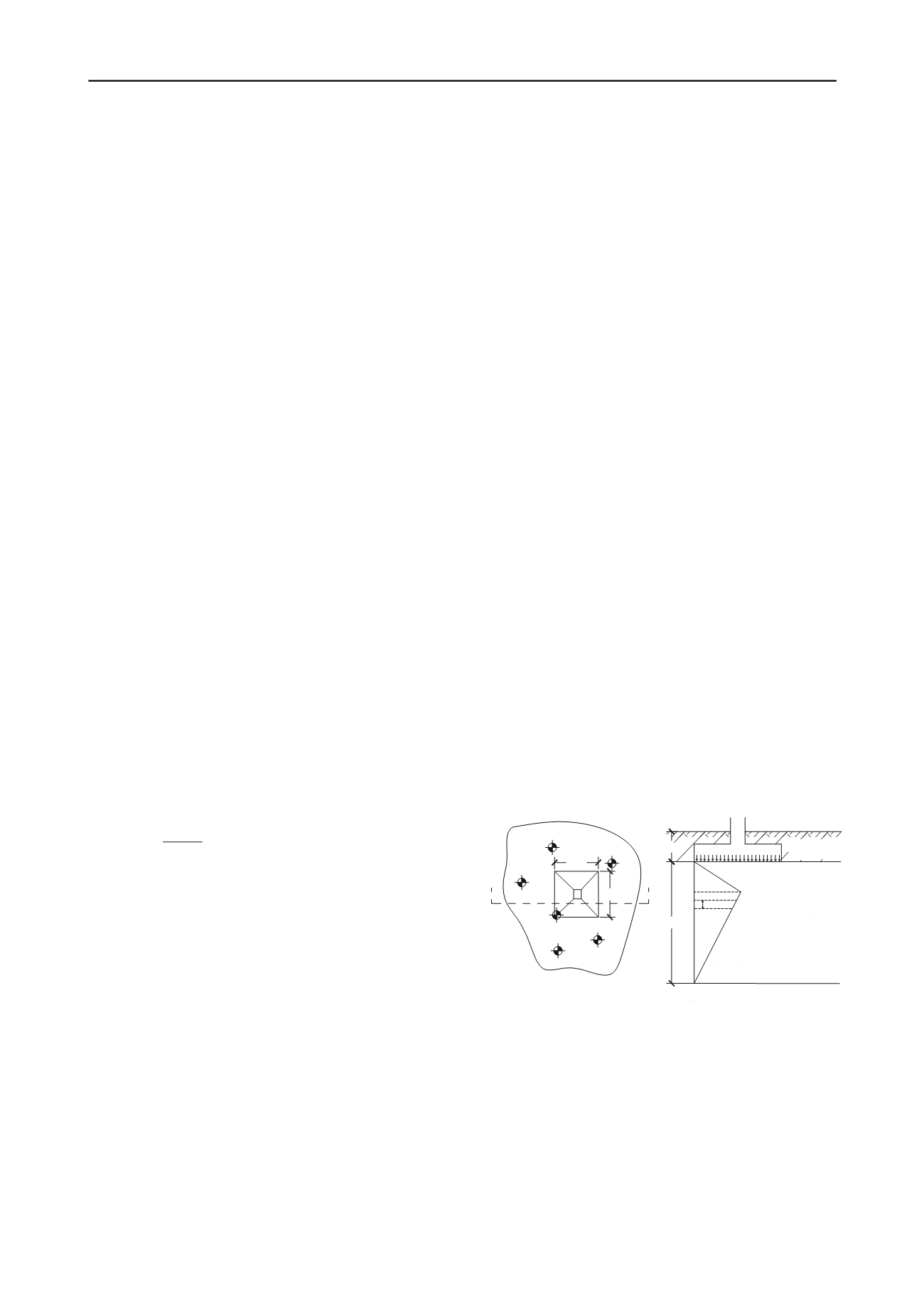
This section presents an example of application of the SOSM
methodology. The case considers one footing with 1600 kN
centrally applied load, size of 2,0m x 2,0m, embedded 1,0m
below ground surface. The subsoil stratum is showed in figure
3. This situation with shallow stratum composed by sand with
varied relative density is a typical soil formation from the
coastal of Vitoria/ES, influenced by the transgression/regression
marine phenomena, occurred in Quaternaries’ period.
Figure 3. Subsoil stratum adopted for the example of application.
n
EV EV
S
S
] [
] [
1
3
1,0m
4,0m
normally consolidated
clean sand
γ = 19 kN/m³
sandy clay fill
γ=16 kN/m³
B/2
20 cm
2B
A
A
CPT-01
CPT-02
CPT-05
CPT-03
2,0m
The results of 06 mechanical cone penetration tests (CPT),
with 20 cm limit interval data, are hypothetically assumed to be
available in a region around the footing, which is represented by
the shown subsoil stratum.
For
Schmertmann’s (1970) equation, sublayer thickness was
set at 20 cm. To account for soil variability in this region is
firstly necessary to analyze statistically the CPT data. For each
sublayer, q mean and variance values must be calculated.
ci
After that, deformability modulus has to be estimated for
each sublayer, through the adopted(s) empirical correlation(s).
Here, it’s assumed the use of only one correlation, which is
given by Schmertmann’s (1970):
(18)
] [
] [
] [
] [
3
2
1
Si
Si
Si
Si
EV EV EV EV
Ci
Si
q E
.2
CPT-04
2,0m
CPT-06
SECTION A-A
PLAN VIEW
The uncertainties in E
Si
can be analyzed by attributing values
to E
Si
variance (V[E
Si
]), or by analyzing the sources of
uncertainties in the E
Si
estimations. Considering that the moduli
E
Si
are estimated from CPT, three sources of uncertainty are
suggested to be accounted for:
(i) The uncertainties due to field measurements (q
ci
, in this
case) – in other words, the sum of inherent soil variability and
equipments/measurement procedures errors of CPT. This
variance is named V
1
[E
Si
].
(ii) The uncertainties due to transformation models – in other
words, the empirical correlations used to transform the field
measurement results (q
ci
) into required design parameters (E
Si
).
This variance is named V
2
[E
Si
];
(iii) Statistical uncertainties – due to limited sampling or
insufficient representative sampling data in the field. This
variance is named V
3
[E
Si
].
The sources of uncertainties represented by V
1
[E
Si
] and
V
2
[E
Si
] are explicit in the E
Si
x q
ci
correlations. The typical form
of those correlations is:
)
] [ .
] [
2
1
Ci
average
Si
qV
EV
] [ .
] [
2
2
V
q EV
average
Ci
Si
(13)
Observe that in equation (13) two variables can contribute
for the uncertainties in E
Si
estimations, which are: q
ci
and α. It
represents the uncertainties V
1
[E
S
] and V
2
[E
S
], as assumed
before. The FOSM method is applied to equation (13) to give
those sources of uncertainties. Then, V
1
[E
S
] e V
2
[E
S
] are:
(14
in which: V[q
ci
] is the sampling variance, calculated using q
ci
results, of the i
th
sublayer, and α
average
is the average or mean α-
value, from the choosed correlations.
(15)
3 EXAMPLE OF APPLICATION
in which: V[α] is the variance of α –values, supposed to be
equally likely. To evaluate V
2
[E
Si
], two or more empirical
correlations are needed or, in other case, it results zero.
The third source of uncertainties evaluated is due to the
representative of sampling data. Assuming that this source of
uncertainties is function only of the amount of sampling (size of
sample), it can be calculated using the following equation
proposed by DeGroot (1986; apud Goldsworthy 2006):
(16)
in which: V
1
[E
S
] is the sampling variance from E
S
results; n is
the number of data obtained from CPT.
Thus, the equation to account for all sources of uncertainties
on the variance of E
Si
, of the i
th
sublayer is:
17)
(
2.5
Further discussions
Comparative analysis has showed that the use of the FOSM
method underestimates the results for COV[E
S
]>30%, reaching
up to 50% error when COV[E
S
]=100%, due to the non-
consideration of the higher orders terms in Taylor‘s series,
while SOSM and MCS methods seems to converge,
approximately, to same results for all COV[E
S
] values.
advantages and limitations of its use. Some advantages are:
Easy application, trough electronic spreadsheets,
without having finite element or advanced calculation
software’s.
It’s very helpful for giving guidance on the sensivity of
design results (Griffiths et al. 2002), outcome from
Schmertmann’s (1970) equation, to variations of
deformability modulus.
Is possible to verify the distribution and the contribution
of settlement variances in the sublayers.
Despite the non-account for spatial correlations or scale
of fluctuation of deformability modulus, the use of
Taylor’s methods is not against safety, as observed
previously by Gimenes and Hachich (1992).
Some limitations are:
It’s assumed a single and isolated footing (i.e. there are
no interaction among strain bulbs of adjacent footings
and no soil-structure interaction effects).
In a foundation SLS analysis is necessary to account for
the variability of other important parameters as:
geometry and load of footings, which were considered
constants for the present study.
Ci
Si
q E
.
On the use of the proposed methodologies, is recommended
that the sublayer thickness be considered as small as possible,
so the influence of tendencies in vertical variability is minimal
(Campanella et al, 1987). For example, in mechanical CPT with
20cm interval data, is indicated to set 20cm for sublayer
thickness, so the vertical variability is already considered in the
subsoil stratification and is not necessary to detrend the data
(since the sublayers are treated as independent from each other).
In this case, the evaluated uncertainties in moduli are only from
horizontal variability of the sublay rs.
This section presents an example of application of the SOSM
methodology. The case considers one footing with 1600 kN
centrally applied load, size of 2,0m x 2,0m, embedded 1,0m
below ground surface. The subsoil stratum is showed in figure
3. This situation with shallow stratum composed by sand with
varied relative density is a typical soil formation from the
coastal of Vitoria/ES, influenced by the transgression/regression
marine phenomena, occurred in Quaternaries’ period.
Figure 3. Subsoil stratum adopted for the example of application.
n
EV EV
S
S
] [
] [
1
3
1,0m
4,0m
normally consolidated
clean s nd
γ = 19 kN/m³
sandy clay fill
γ=16 kN/m³
B/2
20 cm
2B
A
A
CPT-01
CPT-02
CPT-05
CPT-03
2,0m
The results of 06 mechanical cone penetration tests (CPT),
with 20 cm limit interval data, are hypothetically assumed to be
available in a region around the footing, which is represented by
the shown subsoil stratum.
For
Schmertmann’s (1970) equation, sublayer thickness was
] [
] [
] [
] [
3
2
1
Si
Si
Si
Si
EV EV EV EV
CPT-04
2,0m
CPT-06
SECTION A-A
PLAN VIEW
The uncertainties in E
Si
can be analyzed by attributing values
to E
Si
variance (V[E
Si
]), or by analyzing the sources of
uncertainties in the E
Si
estimations. Considering that the moduli
E
Si
are estimated from CPT, three sources of uncertainty are
suggested to be accounted for:
(i) The uncertainties due to field measurements (q
ci
, in this
case) – in other words, the sum of inherent soil variability and
equipments/measurement procedures errors of CPT. This
variance is named V
1
[E
Si
].
(ii) The uncertainties due to transformation models – in other
words, the empirical correlations used to transform the field
measurement results (q
ci
) into required design parameters (E
Si
).
This variance is named V
2
[E
Si
];
(iii) Statistical uncertainties – due to limited sampling or
insufficient representative sampli g data in he f eld. Thi
variance is nam d
3
[E
Si
].
The sources of uncertainties repre ented by V
1
[E
Si
] and
V
2
[E
Si
] are explicit in the E
Si
x q
ci
correlations. The typical form
of tho correlations is:
)
] [ .
] [
2
1
Ci
averag
Si
qV
EV
] [ .
] [
2
2
V
q EV
average
Ci
Si
(13)
Obs rve that in equation (13) two variables can contribute
for the uncertainties in E
Si
estimations, which are: q
ci
and α. It
repre ents the un ertainti s V
1
[E
S
] and V
2
[E
S
], as assume
b fore. The FOSM method is appli to equation (13) to give
tho e sources of unc rtainties. Then, V
1
[E
S
] e V
2
[E
S
] are:
(14
in w ich: V[q
ci
] is the sampling variance, calculated us ng q
ci
results, of the i
th
sublay r, and α
average
is the average or mean α-
value, from the choosed correlations.
( 5)
3 EXAMPLE OF APPLICATION
in which: V[α] s the variance of α –values, supposed to be
equally lik ly. To evaluate V
2
[E
Si
], t o or more empirical
cor lations are needed or, in other case, it results zero.
The third source of uncertaint s evaluated is due to th
repr sentative of sampli g data. Assuming that this source of
uncertainties is function only of the amount of sampling (size of
sample), it can be calculated using the following equation
proposed by DeGroot (1986; apud Goldsworthy 2006):
(16)
in which: V
1
[E
S
] is the sampling variance from E
S
results; n is
the number of d ta obtained from CPT.
Thus, the equation to account for all sources of uncertainties
on the variance of E
Si
, of the i
th
sublayer is:
17)
(
2.5
Further discussions
Compara ive analy is has showed that the use of the FOSM
method underestimates the results for COV[E
S
]>30%, reaching
up to 50% error when COV[E
S
]=100%, due to the non-
consideration of the higher orders terms in Taylor‘s series,
while SOSM and MCS methods seems to converge,
approximately, to same results for all COV[E
S
] values.
It has been also observed that the depth where the major
variance contribution occurs is highly dependent of the E
Si
values, with strong influence of the I
Z
distribution factor, from
Schmertmann’s (1970). So, the significance of settlement
variance contribution (V[ρ
i
]), of the i
th
sublayer, in total
settlement variance (V[ρ]) increases as the lower the mean
value of E
Si
and the closer the sublayer is to I
Zmax
depth.
As being simplified methods, is important to summarize the
advantages and limitations of its use. Some advantages are:
Easy application, trough electronic spreadsheets,
without having finite element or advanced calculation
software’s.
It’s very helpful for giving guidance on the sensivity of
design results (Griffiths et al. 2002), outcome from
Schmertmann’s (1970) equation, to variations of
deformability modulus.
Is possible to verify the distribution and the contribution
of settlement variances in the sublayers.
Despite the non-account for spatial correlations or scale
of fluctuation of deformability modulus, the use of
Taylor’s methods is not against safety, as observed
previously by Gimenes and Hachich (1992).
Some limitations are:
It’s assumed a single and isolated footing (i.e. there are
no interaction among strain bulbs of adjacent footings
and no soil-structure interaction effects).
n a foundation SLS analysis is ne ssary to account for
the va iability of other important paramet rs as:
geom try nd load of footings, which were considered
constants for the present study.
Ci
Si
q E
.
On the use of the proposed me hodol gies, is re mmended
that the sublayer thickness be considered as small as possible,
so the influence of te den ies in vertical variabili y is minimal
(Campanella et al, 1987). For example, in mechanical CPT with
20cm interval data, is indicated to set 20cm for sublayer
thickness, so the vertical variability is already considered in the
subs il strat fication and is not necessary to detrend the data
(since the ublayers are treated as ndep ndent from each othe ).
In this case, the evaluated uncert ties in moduli are only from
horizontal variability of the sublayers.
This section presents an example of application of the SOSM
methodology. The case considers one footing with 1600 kN
centrally applied load, size of 2,0m x 2,0m, embedded 1,0m
below ground surface. The subsoil stratum is showed in figure
3. This situation with shallow stratum composed by sand with
varied relative density is a typical soil formation from the
coastal of Vitoria/ES, influenced by the transgression/regression
marine phenomena, occurred in Quaternaries’ period.
Figure 3. Subsoil stratum adopted for the example of application.
n
EV EV
S
S
] [
] [
1
3
1,0m
4,0m
normally consolidated
clean sand
γ = 19 kN/m³
sandy clay fill
γ=16 kN/m³
B/2
20 cm
2B
A
A
CPT-01
CPT-02
CPT-05
CPT-03
2,0m
The results of 06 mechanical cone penetration tests (CPT),
with 20 cm limit interval data, are hypothetically assumed to be
available in a region around the footing, which is represented by
the shown subsoil stratum.
For
Schmertmann’s (1970) equation, sublayer thickness was
set at 20 cm. To account for soil variability in this region is
firstly necessary to analyze statistically the CPT data. For each
sublayer, q mean and variance values must be calculated.
ci
After that, deformability modulus has to be estimated for
each sublayer, through the adopted(s) empirical correlation(s).
Here, it’s assumed the use of only one correlation, which is
given by Schmertmann’s (1970):
(18)
] [
] [
] [
] [
3
2
1
Si
Si
Si
Si
EV EV EV EV
Ci
Si
q E
.2
CPT-04
2,0m
CPT-06
SECTION A-A
PLAN VIEW


