2475
Technical Committee 211 /
Comité technique 211
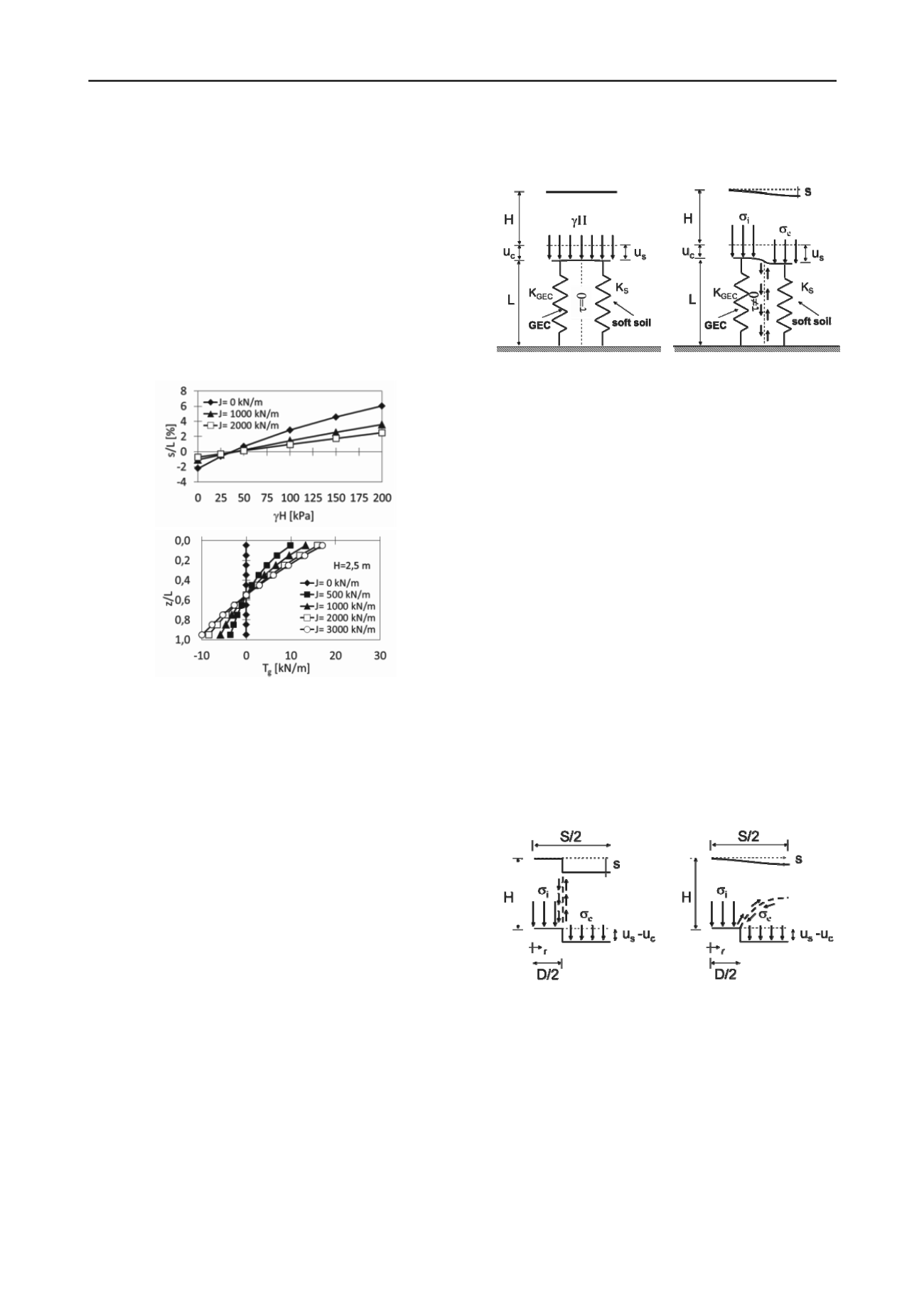
which negative settlements (i.e. uplift) are obtained. This
meaningless result is obtained even for a nil value of the
stiffness J of the encasing geomembrane. This essentially
derives from the assumption concerning the soil within the
column which is imposed to be at the critical state along the
entire column (similar results have been observed even for
other values of L and S/D, but they have not been reported here
for the sake of brevity). This is evident when the tensile force T
g
in the encasing geomembrane along depth z of the column is
considered (Figure 3b, where the case of a shallow embankment
is analyzed): at the base of the column the vertical stress is not
sufficient to induce an active state of stress, and the only
possibility for the column to satisfy the hypothesis of critical
state is to reduce its radius, thus inducing a compression (i.e.
T
g
<0) in the encasing geomembrane.
a)
b)
Figure 3. EBGEO: evaluation of (a) settlements and (b) tensile force in
the encasing geomembrane.
3 A DISPLACEMENT BASED DESIGN APPROACH
In order to overcome the above cited limitations, a consistent
and physically based design would require a fully displacement
based approach. As was theoretically outlined by Galli and di
Prisco (2011), with reference to a single axisymmetric cell (i.e.
to a single column together with the surrounding soft soil), the
foundation system can be assumed to be composed by two
coupled springs, one representing the GEC and the second
representing the surrounding soft soil. The two springs work in
parallel if and only if the base of the embankment can be
considered to be rigid and no differential settlements to arise
(Figure 4a). Under this hypothesis, the vertical stress at the base
of the embankment is thus uniformly distributed (in Figure 4a γ
stands for the unit weight of the granular material constituting
the embankment), no differential settlement are observed at the
top of the embankment, and no shear stresses develop at GEC-
soil interface. The values of vertical stress both in the column
and in the soil then can be assumed to depend exclusively on the
axial stiffness of the column (K
GEC
) and on the vertical
compressibility of the soft soil (represented in Figure 4a by a
global stiffness K
S
).
Real embankments, however, are characterized by a
deformable base (Figure 4b), and different values of settlement
are expected for the top of the column (u
c
) and for the soil (u
s
)
at the base of the embankment. Consequently: (i) vertical
stresses are redistributed at the base of the embankment
between the internal zone of the cell (above the column,
characterized by an average stress
i
) and the external one (a
circular crown above the soil, characterized by an average stress
e
) due to the so called arch effect, (ii) shear stresses are
activated at GEC-soil interface, and (iii) differential settlements
are expected even at the embankment top.
a)
b)
Figure 4. Mechanical response of the foundation system in case of (a)
rigid and (b) deformable embankment.
From a modeling point of view, by assuming an engineering
approach based on generalized variables, the mechanical
behavior of the embankment can be described by means of a
generalized constitutive relationship between the average
stresses at the base of the embankment and the differential
settlements (assumed to be uniform) between the column and
the soil:
c s
e i
uuf
,
(1)
where the values of
i
and
e
must satisfy the equilibrium
with respect to the weight of the embankment on the unit cell
2
2 2
2
SH DS D
e
i
.
(2)
The constitutive relationship f can be in general assumed to
be described by means of a non-linear curve, whose average
stiffness depends (i) on the geometry of the system (S, D, H),
(ii) on the mechanical properties of the granular material
constituting the embankment and (iii) on the geo-reinforcements
at the base of the embankment. Its limit value corresponds
instead to the activation of a failure mechanism within the
embankment. Depending on the formation of the arch effect,
either a “punching” failure mechanism, or a “dome” failure
mechanism, with no (or very limited) superficial differential
settlements, might develop (Figure 5a-b).
a)
b)
Figure 5. Failure within the embankment: (a) punching mechanism and
(b) domed mechanism due to arch effect.
The pattern of superficial differential settlement s=s(r) could
then be formally described by a transfer function, ranging from
a discontinuous function (in case of punching), to a smooth
function (in case of formation of the arch effect).
4 NUMERICAL ANALYSES ON SETTLEMENT PROFILE
In order to investigate the settlement distribution s(r) at the top
of the embankment for increasing values of H, some
preliminary finite difference numerical analyses have been
performed by means of the commercial code FLAC. An
axisymmetric geometry has been chosen in order to model the
cell, and the simplifying hypothesis of rigid column has been


