2206
Proceedings of the 18
th
International Conference on Soil Mechanics and Geotechnical Engineering, Paris 2013
anchors and piles during the stabilization of the sliding slope. It
was suggested that the post-stabilized slope should also be
monitored for another dry season of 2012 and another wet
season of 2013.
The paper mainly introduced the instrumentation system of
fielding monitoring of the sliding slope. It also introduced the
preliminary analysis of the variations of rainfall intensity, soil
moisture content, matric suction, ground water level, slope
deformation during the dry season of 2011 and the wet season
of 2012 before the stabilization of the sliding slope.
2 SITE CONDITIONS
The site is a natural hillside terrain covered by a lot of
vegetation. The section was originally a gentle slope and then it
was cut to accommodate the footpath for the main road. Ground
investigation work was carried out during instrument
installation. The site ground as revealed by the ground
investigation is mainly residual soil, completely decomposed
granite (CDG) and highly decomposed granite (HDG), which
are underlain by moderately decomposed granite (MDG) and
slightly decomposed granite (SDG).
Laboratory tests were carried out on the soil samples
obtained at the sliding slope during the site investigation. The
soil, as revealed by site investigation, is completely
decomposed medium-grained granite and can be classified as a
very weak to weak, light brown to brown, silty/clayey sand. The
laboratory program to characterize the soil properties included:
(1) Bulk density, (2) Dry density, (3) Specific gravity, (4)
Atterberg limits and (5) Particle size distribution.
Part of the laboratory tests results are summarized in Table 1.
Table 1. Soil properties for the sliding slope.
Bulk density (Mg/m3)
1.76~1.93
Dry density (Mg/m3)
1.44~1.54
Specific gravity
2.627~2.655
Void ratio
0.7314~0.8443
Porosity
0.42~0.46
Liquid limit (%)
31.5~44.3
Plasticity index (%)
12~23
3 INSTRUMENTATION SYSTEM
The instruments included soil moisture probes to measure
volumetric water content, tensiometers to measure matric
suction (negative pore water pressure), open standpipes and
piezometers to measure ground water level and positive pore
water pressure, inclinometers to measure the lateral ground
movements, and a rain gauge to measure rainfall intensity.
The philosophy for instrumentation design was as follows:
The moisture probes and tensiometers were installed in the
shallow depth to monitor volumetric water content and matric
suction in the unsaturated zone of the soil. The open standpipes
and piezometers were installed in both the shallow depth and
greater depth to monitor both perched and deep ground water or
positive pore pressure in the saturated zone of the soil. The
inclinometers were installed in the soil to monitor horizontal
deformation of the sliding slope. The rain gauge was installed to
monitor the specific rainfall intensity of the monitored sliding
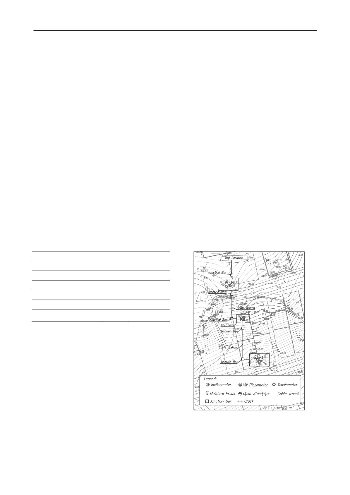
slope. Figure 1 shows instrumentation layout plan.
A total of six moisture probes were used to measure
volumetric water contents inside different parts of the sliding
slope (Figure 1). Three moisture probes were installed in
borehole M1 (M1-1 (1m), M1-2 (2m) and M1-3 (3m)) at depths
of 1 m, 2 m and 3 m, respectively, at the toe of the slope. The
other three moisture probes were installed in boreholes M3
(M3-1 (1m), M3-2 (2m) and M3-3 (3m)) at depths of 1 m, 2 m
and 3 m, respectively, near the crest of the slope. A total of six
tensiometers were used to measure matric suction at different
locations of the sliding slope (Figure 1). Three of them were
installed in boreholes T1 (T1-1 (1m), T1-2 (2m) and T1-3 (3m))
at depths of 1 m, 2 m, 3 m and 4 m, respectively at the toe of the
sliding slope. The other three were installed in boreholes T3
(T3-1 (1m), T3-2 (2m) and T3-3 (3m)) at depths of 1 m, 2 m, 3
m and 4 m, respectively, near the crest of the sliding slope. A
total of three open standpipes were used to measure ground
water levels at different locations of the sliding slope (Figure 1).
A total of three vibrating wire piezometers (P1, P2 and P3) were
used to measure positive pore water pressures at different
locations of the sliding slope (Figure 1).
A total of three
inclinometer tubes (IN1, IN2 and IN3) were used to measure the
lateral ground movements at different locations of the sliding
slope (Figure 1).
One 0.5 mm “tipping bucket” rain gauge with
internal logger was used to monitor the rainfall intensity of the
monitored slope site automatically (Figure 1).
Ground water levels in the open standpipes were monitored
manually with the help of a dipmeter. An automatic data
acquisition system was set up for the sliding slope to monitor
moisture content, matric suction, positive pore water pressure
and horizontal deformation continuously. The automatic data
acquisition system consists of sensors, cables, data loggers and
power supplies. An instrumentation hut was constructed at the
top of the sliding slope to house the data loggers and power
supplies. The data loggers were configured to collect data at
15/30-min intervals and the data were transmitted to both the
office in the site and the office in Shenzhen instantly via
wireless data transition system.
Figure 1. Boreholes and instrumentation layout plan.


