2194
Proceedings of the 18
th
International Conference on Soil Mechanics and Geotechnical Engineering, Paris 2013
3 MONITORING OF SLOPE MOVEMENTS
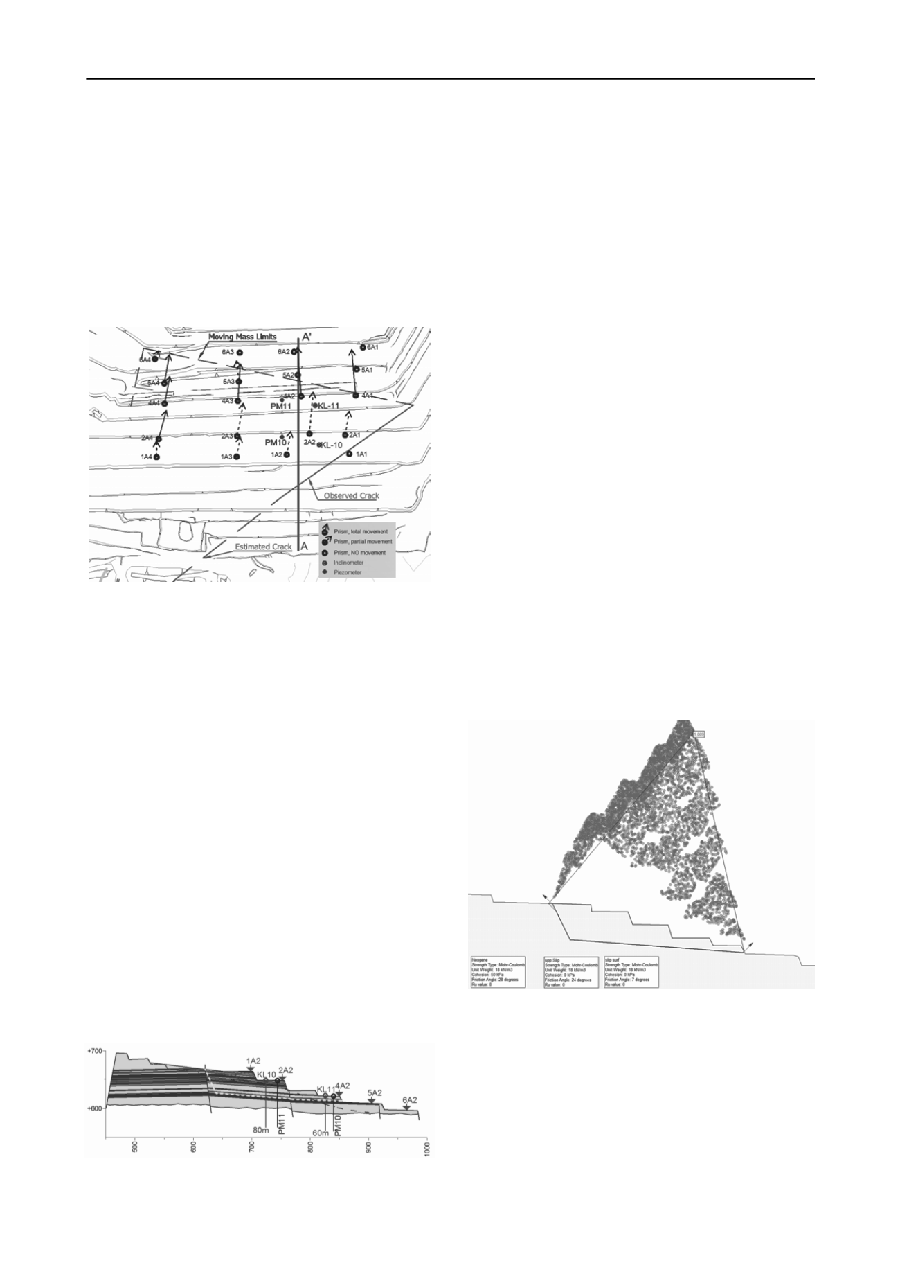
At the end of 2010, tension cracks were observed at the crest of
the Southeast mine slopes and visually observed horizontal
transverse movements at the toe under prisms 5A3 and 6A4.
Although this is usual in large and deep open pit mines,
nevertheless, 20 prism monitoring stations, two inclinometers
(KL-10, 11) and two piezometers (PM-10, 11) were installed on
the slopes. The locations of the instruments are shown in Figure
2 together with the limits of the moving mass.
Prism measurement records were made available between
January 2012 and up to the writing of this paper (Sept. 2012).
Figure 2. Monitoring equipment and trends on Southeast slopes
Initially the measurements were executed with a lower accuracy
total station and only the “sloping distance” between the prism
and the measurement base was evaluated. Due to the complexity
and criticality of the situation, a new robotic total station of high
accuracy (0.5cc) replaced the old one. With the new total station
the movement vectors could easily be measured and evaluated.
The use of the robotic total station eliminated the surveyor
operation error and the high accuracy significantly reduced the
horizontal and vertical angular measurement error.
Due to the high rate of movement, few measurements were
taken from the inclinometers before they were sheared off.
From inclinometer KL-10, six measurements were obtained in a
period of one month which recorded a total displacement
100mm at 27m depth from ground surface. Inclinometer KL-11
recorded only three measurements in a period of 11 days, with
maximum displacement 150mm at 9m depth. The two
piezometers could only be measured twice due to operational
reasons and recorded water table elevation at 18.4m in PM-10
and 9.9m in PM-11. A precise water table could not be
estimated based on the piezometer measurements because of the
number of measurements and since the faces of the slopes were
found dry. Piezometric conditions and water pressures are very
difficult to model with a high degree of accuracy in mines
(Sullivan, 2007) mainly due to the presence of multiple perched
aquifers. Figure 3 shows a geological cross section with the
monitoring equipment and the failure surface location (white
line). Dark zones indicate the lignite beds.
Figure 3. A-A’ cross section with monitoring locations
4 EVALUATION OF SLOPE MOVEMENTS
The operation of Mavropigi mine is very important for the
power supply of Greece and uninterrupted operation is often
critical. Mining operations may take place even in moving
slopes, as long as safety of personnel and equipment is satisfied.
Zavodni (2000) states that “
mining operations can proceed
safely with minimum interruption if failure mechanisms are
understood and slopes are properly monitored
” even in moving
slopes. The way to assess if a “moving slope” can be mined
safely is to determine if the slope movement is regressive or
progressive. A regressive movement is cyclic decelerated while
a progressive movement exhibits overall acceleration without
appreciable deceleration intervals (Zavondi, 2000). In regressive
movements, mining operation can continue after incorporating a
monitoring system. If monitoring data indicate a progressive
type of movement the operations are in danger of imminent
collapse. The question posed to the Geotechnical Engineer is to
determine the type of movement that characterizes each
particular slope. The failure mechanism needs to be understood
and a sufficient quantity of qualitative measurements is
required. In the literature, most case studies are analyzed after
an incident and with adequate monitoring data and the type of
movement is identified (Ryan & Call 1992). At the Mavropigi
mine, decisions had to be made based on the day to day data
becoming available without a priori having a large amount of
data that could be used to determine the type of movement.
Initially, based on the geological model of the area, the
visual observations of the cracks in the crest and the
translational surface located by the inclinometers, a limit
equilibrium model was analyzed to evaluate if the movement
was possible and to back calculate the material properties of the
shear surface. Based on back analysis (Figure 4) it was found
that a sliding surface was possible with residual friction angle of
φ
r
=7
o
for the near horizontal surface and φ’=24
ο
for the back
scarp. These values were considered to be the lower bounds
since no water pressures were introduced and were in good
agreement with the laboratory ones provided in Table 1 for the
area.
Figure 4. Back analysis of the sliding surface
From the geological model, the inclinometer readings and the
back analysis it was found that the movement is taking place in
a failure shear zone (thin high plasticity clay interlayer) with an
inclination of about 4-5
o
. Based on this information an initial
estimate was made that the movement could be of the regressive
type based on the recommendations by (Zavodi and Broadbent,
1980), by which movements are deemed regressive when taking
place on a surface with a lower angle in relation to the slope
face inclination and the shear resistance (friction angle) of the
material. Initial remediation measures consisting of excavating
part of the top two benches were analyzed with the same data.
Analysis showed that the FS became 1.06 which was considered


