1090
Proceedings of the 18
th
International Conference on Soil Mechanics and Geotechnical Engineering, Paris 2013
σ
- u
a
is defined as the net normal stress. When the matric
suction decreases or the net normal stress increases, the volume
of the unsaturated soil decreases.
The volume change of an unsaturated soil can be represented
by the net normal stress and the matric suction. The constitutive
relationship that takes into consideration of net normal stress
and the matric suction is the following (Fredlund and Rahardjo
1993):
(1)
where
ε
v
is the volumetric strain, d
ε
v
is the volumetric strain
change for each increment,
μ is Poisson’s ratio
, E is the
modulus of elasticity and H is the modulus of elasticity for the
soil structure with respect to a change in matric suction.
2.2 Elastic wave velocities
Physical characterization of soil using shear waves and
compression waves is commonly used in the geotechnical field.
The physical characteristics of the soil structure can be
represented by Young's modulus (E) and the shear modulus (G).
The shear modulus can be determined from the shear wave
velocity, using the following equation:
(2)
where
ρ
is the density of the soil and V
s
is the shear wave
velocity. Young's modulus, E, can be determined from the shear
modulus, G:
1 2
G E
(3)
where i
s Poisson’s ratio. Poisson's ratio can be
determined from
the shear wave velocity (V
s
) and the compression wave velocity
(V
p
).
(4)
The change in the volume of the soil can be predicted using
the modulus of elasticity, with the shear modulus of elasticity
and Poisson's ratio substituted into Equation (1).
(5)
where the H value is E/0.17, as suggested by Fredlund and
Rahardjo (1993). Thus, the void ratio change can be estimated
from the compression and shear wave velocities.
3 LABORATORY TESTING
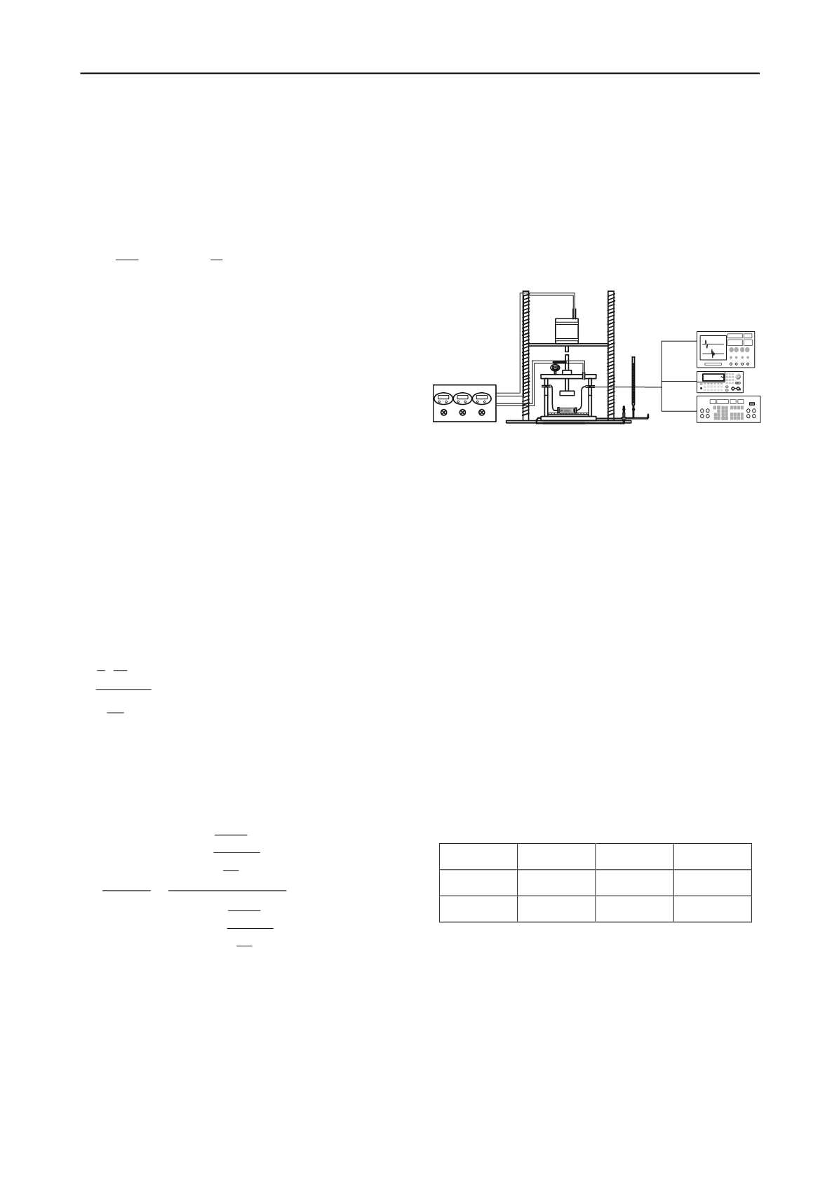
3.1 VPPE system
In this study, a modified volumetric pressure plate extractor
(VPPE) was used. A schematic diagram of the modified system
and its peripheral electronics is shown in Figure 1. The
modified VPPE system was used to apply axial stresses and
measure elastic waves. Axial stresses were applied through the
center rod, as shown in Figure 1.
Figure 1. Modified VPPE system and peripheral electronics
The regulator system on the left side of Figure 1 controls the
matric suction and axial stress. The regulator system consists of
three regulators. Two of them are used to control the matric
suction, and the third controls the axial stress. The settlement
was measured by a digital dial gauge attached to the rod that is
used to apply axial stress.
The VPPE system also included a load cell to calculate the
axial stress. Elastic waves are generated and detected using
bender elements and piezo disk elements. The electronics on the
right side of Figure 1 are a function generator, a filter amplifier
and an oscilloscope, used to generate and detect shear and
compression waves. Single sine waves were used for generation
and detection of shear and compression waves (Lee and
Santamarina 2005, Lee and Santamarina 2006).
3.2 Test procedures
Two types of soil specimens were used for this study. First, a
uniform-grain-sized sand with a mean particle diameter of 0.45
mm were used. Second, a sand
–
silt mixture with a silt volume
fraction of 20% was used. The physical properties of the
specimens are summarized in Table 1. After partially saturated
specimens were placed into the rectangular cell, which was
placed on the ceramic plate of the VPPE, the VPPE was closed
and matric suction was applied
Table 1. Physical properties of the soil samples.
Soil type
G
s
e
max
e
min
Sand
2.62
0.82
0.56
Sand
–
silt
2.62
0.80
0.42
As matric suction is applied, the degree of saturation of the
an unsaturated soil changes. Note that vertical axial stress was
applied to control the mean normal stress. Elastic waves were
continuously measured based on the matric suction. After the
matric suction was applied, the soil specimen being tested
gradually reached equilibrium. The elastic waves were
measured at 1, 4, 9, 16 and 25 minutes and 1, 2, 4, 6 and 24
hours after the application of matric suction. The shear and
compression wave velocities were obtained at each degree of
saturation. After the maximum matric suction was applied, the
matric suction was gradually decreased.
S
2
P
S
2
P
1 V -1
2 V
μ
=
V -1
V
v
mean a
a w
1-2
μ
3
d
ε
=3
d
σ
-u + d u -u
E
H
2
P
2
S
2
P
2
S
a w
mean a
2
P
2
2
S
S
2
P
2
S
0.5V -1
V 1-2
V -1
V
3 u -u
Δ
e=
+3
×
σ
-u
H
0.5V -1
V
2
ρ
V 1+
V -1
V
SIGNAL
Regulator system
Improved VPPE system
Electronics system
2
S
G=
ρ
×V


