1079
Technical Committee 106 /
Comité technique 106
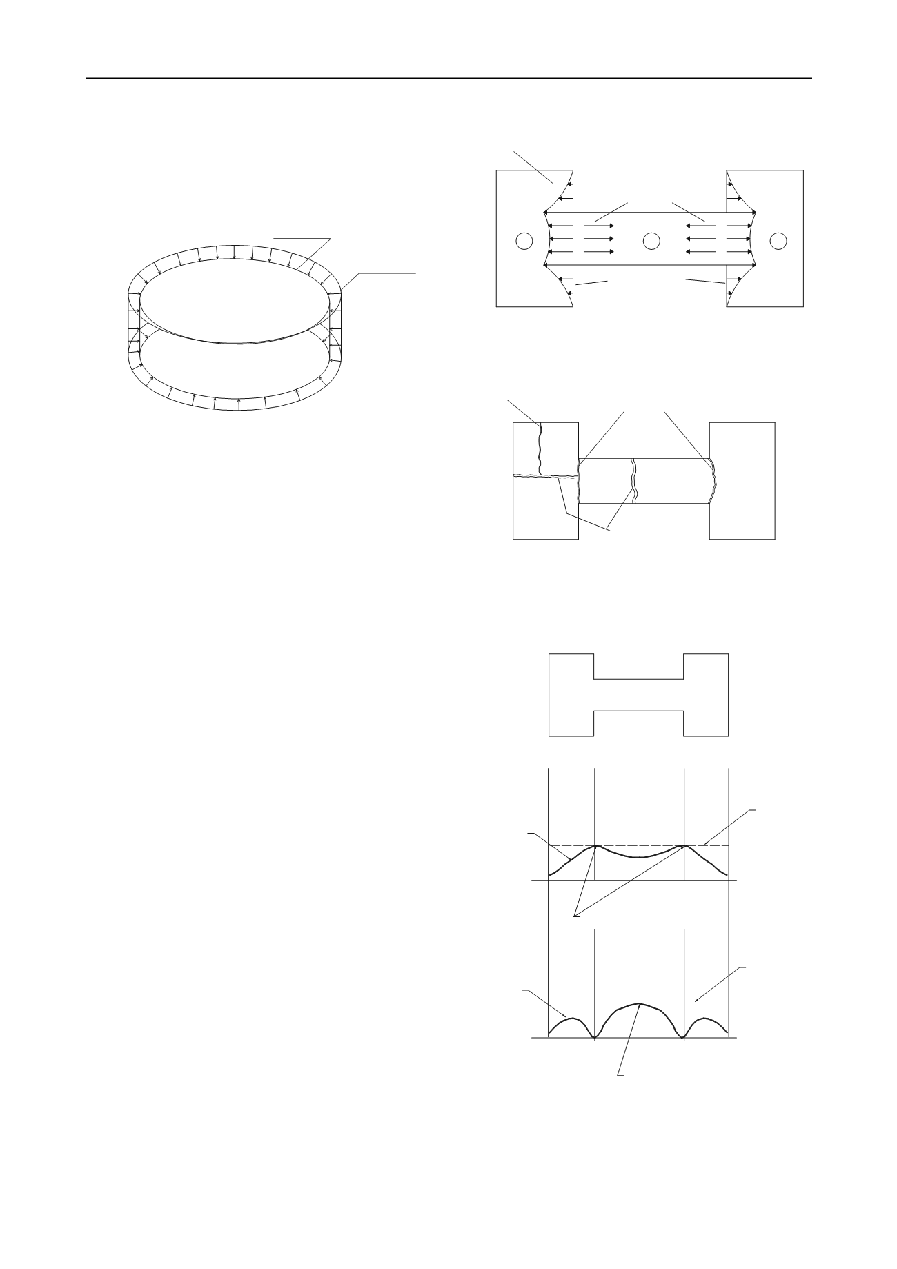
Cylindrical shape is convenient to ensure uniform drying and
homogeneous contractions, however if the base of the mould is
not smooth and friction between the mould and the sample
develops during desiccation, nonhomogeneous tensile forces are
generated producing complex drying patterns.
dry sample
wet sample
Figure 5. Sketch of a uniform and free contraction of a homogeneous
sample subjected to drying. Under these conditions, cracks are not
expected.
Stress changes are generated as a result of the forces induced
when the soil tends to shrink but the boundary conditions
restrict the free shrinkage. Figure 6 represents a simple picture
of the forces that may progress in the different sectors of the
sample during the desiccation process. Abu-Hejleh and
Znidarcic (1995) and Konrad and Ayad (1997) proposed similar
patterns for desiccation cracks formation in clayed soils
subjected to one-dimensional consolidation and contraction
caused by suction increments. In the central sector (sector 2)
action forces tend to occur due to the contraction of the sample
and these forces are counterbalanced by the reaction forces
generated in the extremes of the sample (sectors 1 and 3) where
the reaction walls play an important role in avoiding the
contraction of the soil. Primary cracks tend to initiate precisely
in the vertices of these reaction walls (points a, f, g or l, in
Figure 6) because it is where an important stress concentration
occurs. Primary cracks progress in a direction perpendicular to
the main action forces, as sketched in Figure 7.
Once the primary cracks have been completely developed,
shrinkage continues and new stress conditions appear in the
different sectors of the sample. In sector 2 (Fig. 6) action forces
are directed to the center of the sample trying to produce
contraction or length reductions whereas reaction forces are
generated by the friction between the soil and the base of the
mould avoiding the sample contraction. As a combination of the
action and reaction forces, non-uniform tensile stresses are
mobilized along the sample. As it is illustrated in Figure 8
primary cracks appear at the points where mobilized tensile
stress equals the tensile strength of the soil (points b and d). In
the points a and e the mobilized tensile stress are low because
restrictions to contraction are not so strong. On point c some
restrictions to shrinkage are produced by the base and sides of
the mould and a tensile stress is mobilized but of lower value
than stress on points b and d. For that reason sample does not
crack at this point.
As soon as primary cracks are completely developed, the
sample stress distribution changes drastically and a sketch of the
possible distribution is depicted in the lower part of Figure 8.
This stress distribution may explain the occurrence of secondary
cracks in the middle of the sample (point c) generated by the
restriction to shrinkage produced mainly by the base of the
mould. In this point mobilized tensile stress equals tensile
strength of the sample.
1
2
3
c
d
e
f
a
b
l
k
j
i
h
g
reaction forces
action forces
reaction walls
Figure 6. Conceptual representation of the forces that may be developed
for producing primary cracking in the sample.
tertiary crack
primary crack
secundary cracks
Figure 7. Position and orientation of primary, secondary and tertiary
cracks in the drying test.
a b
c
d e
Tensile
Strength
Point of initiation of primary cracks
PRIMARY
CRACKING
SECONDARY
CRACKING
Mobilized
tensile
stress
Tensile
Strength
Mobilized
tensile
stress
Point of initiation of secondary cracks
SOIL SAMPLE
Figure 8. Conceptual stress distribution in the sample for producing
primary and secondary cracking.
The tertiary cracks shown in Figure 3 could be generated in a
similar way than the secondary crack. For that reason the cracks


