656
Proceedings of the 18
th
International Conference on Soil Mechanics and Geotechnical Engineering, Paris 2013
3.
SELECTION OF DESIGN PROCESS
Among the various methods studied, it was considered that the
equivalent pier concept was found to be more suitable. The
applicability of the equivalent pier theory to pled raft analyses
has been established by Horikosh (1995) But the study was
restricted only to a small pile group placed in the center of the
raft , placed on a over consolidated clay layer. Although the
study has produced very important and useful data, the
applicability needs to be validated with other available results
from a general soil profile. In this particular study the results of
two such cases one from the observational study conducted on
an instrumented piled raft supporting a 12 storeyed building and
the other from the parametric study conducted independently
are reanalyzed using equivalent pier concept.
In this particular case the ratio Le/L namely the ratio of the pier
length to the pile works out to unity and hence the equivalent
length of the pier is taken to be the same as that of the pile.
Once the piles are replaced by a pier then the solution for the
single pile can be applied to estimate the load settlement
characteristics, and the load sharing response; the load shared
by the pier becomes the load shared by the pile group. With this
idealisation it is possible to run the analyses as an axisymmetric
two dimensional problem.
4.
VALIDATION
In order to establish the applicability of the equivalent pier
theory two cases were considered for which published results
are available. The models were selected, one from a parametric
study carried out analytically and the other model was from an
observational study carried out on the behaviour of piled raft
supporting a 12 storied structure.
4.1 Validation based on numerical study
Extensive parametric studies have been carried out in Griffith
university Gold Coast campus and the results had been
published by Oh etal.,( 2008 ).These studies had been based on
the general soil profile compiled from the number of
geotechnical investigation data collected. A 9 pile group (3x3)
with 5d spacing has been considered The spacing of the piles
considered is 5d (d
–
diameter of the pile). The d/t ratio is taken
as unity and accordingly the raft thickness and the pile diameter
have been taken as 800mm. The general soil profile comprises
of 13m thick medium dense to dense sand layer, followed by
3m thick highly compressible organic layer termed as peat. This
layer is followed by dense sand and hard clay. The Es values of
various layers have been taken based on the N- values from the
standard correlations. The equivalent pier modulus is taken
from the expression,
E
eq
= E
s
+(E
p
-E
s
)A
t
/A
g
(1)
Where Eeq is the equivalent pier modulus, Es is the elastic
modulus of the soil, Ep is the elastic modulus of the pile, At is
total cross sectional area of the pile , and Ag is the plan area of
the pile group. The pier considered along with the parameters is
presented in Figure 1.
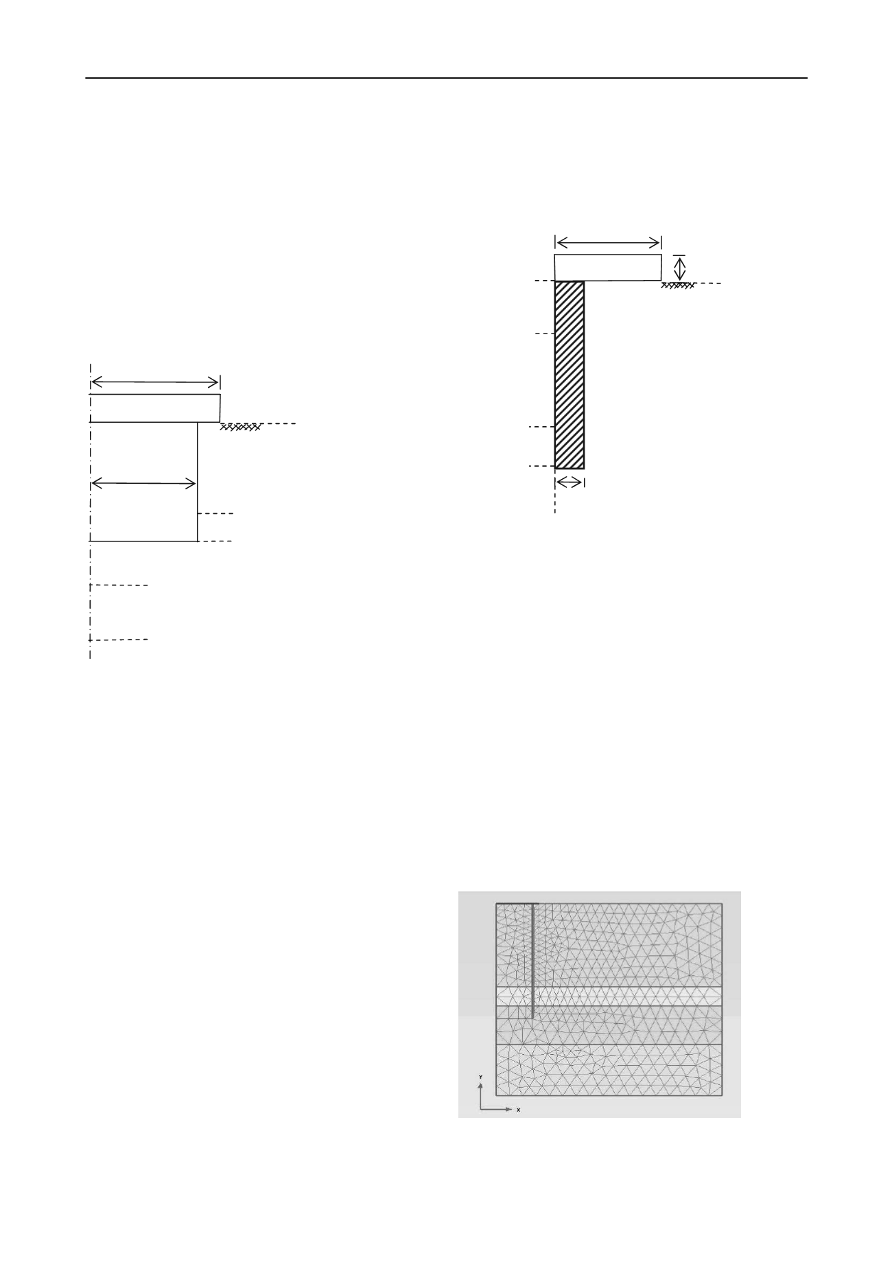
4.2 The observational study
As a part of an extensive research programme, a 12 storeyed
commercial cum residential apartment was designed and
supported on piled raft (Balakumar and Ilamparuthy ) was
instrumented and monitored .The piled raft system comprised of
93piles of 600mm diameter and 14M deep from the bottom of
the raft. The raft thickness was 600mm so that the d/t ratio was
maintained as unity. The layout of piles and other pertinent data
are given in earlier publications .A two pile groups with a
tributary raft diameter of 6m was converted into an equivalent
pier and was loaded in small increments till the settlement
reached 100mm. The pier was resting in a medium dense to
dense sand. The details of the pier,and the geotechnical
parameters together are presented in Figure 2.The analyses in
both the cases were carried out with Plaxis 2D the model and
the mesh are given Figure 3.
Figure 1. Pier & geotechnical data (numerical study)
E for raft = 2.74 x 10
4
MN / m
2
16.00 m
Peat
Ɣ = 0.3 ; s = 25 kN/m
2
= 17 kN/m
3
; Es = 8 MN / m
2
Dense Sand
Ɣ = 0.3
= 36º ;
= 20 kN/m
3
; Es = 35 MN / m
2
Stiff to Hard clay
Ɣ = 0.3 ; s = 80 kN/m
2
= 19 kN/m
3
; Es = 20 MN / m
2
22.00 m
22.00 m
d / 2
D / 2 = 5.65
Dense Sand
Ɣ = 0.3
= 36º
= 20 kN/m
3
; Es = 30 MN / m
2
C / L of PIER
0.0
13.00 m
0.00 m
4.00 m
11.00 m
14.00 m
650 mm
PIER
Sandy silty clay
c = 0.2kg/cm
2
;
= 25º
= 1.6 t/m
3
; E = 50 N / mm
2
Clayey silty sand
c = 0.1kg/cm
2
;
= 27º
= 1.7 t/m
3
; E = 50 N / mm
2
= 34º ;
= 1.8 t/m
3
E = 60 N / mm
2
Very dense strata
E = 70 N / mm
2
600 mm
3000 mm
Figure 2. Observational study
Figure 3. Typical mesh PLAXIS 2D


