


 81 / 479

Proceedings of the 18
th
International Conference on Soil Mechanics and Geotechnical Engineering, Paris 2013, volume 6, 2016
curves (as well as the
q-z
p
pile tip strength curve). The GOUPEG
Program was validated by comparing the interaction coefficients
F
obtained with well-known solutions within the elastic
continuum of Poulos and Davis (1990).
5.3.2 Interpretation of the Rueil-Malmaison tests
These tests were conducted on 4 vertical micropiles: 1 isolated
micropile, and a group of 3 micropiles spaced 1 m apart and
pulled in tension. These micropiles were composed of steel tubes
with: diameter B = 89 mm, a free length of 14 m in the alluvia,
and a sealed length of 5 m in the underlying chalk (B = 125
mm). They were instrumented in 8 sections with the LCPC
removable extensometer in order to determine friction along the
shaft. Several tensile loading calculations were performed with
GOUPEG; each time the skin friction mobilization laws applied
were those of Frank and Zhao. For the interaction between
micropiles and use of Mindlin solutions, a Young's modulus of
E=10 E
M
(E
M
: pressuremeter modulus) was adopted.
Fig. 7: Comparisons between measured and calculated tensile loading
curves of grouped micropiles (Rueil-Malmaison tests)
Figure 7 provides comparisons between the loading curves
measured at the top of each micropile in the group and the
curves calculated with GOUPEG, according to 2 hypotheses for
the limit skin friction (I: average value measured on the isolated
micropile; and II: average value measured for the group as a
whole). These results are satisfactory, in recognizing that the free
length of the isolated micropile is less than 14 m due to a rise in
the level of grout.
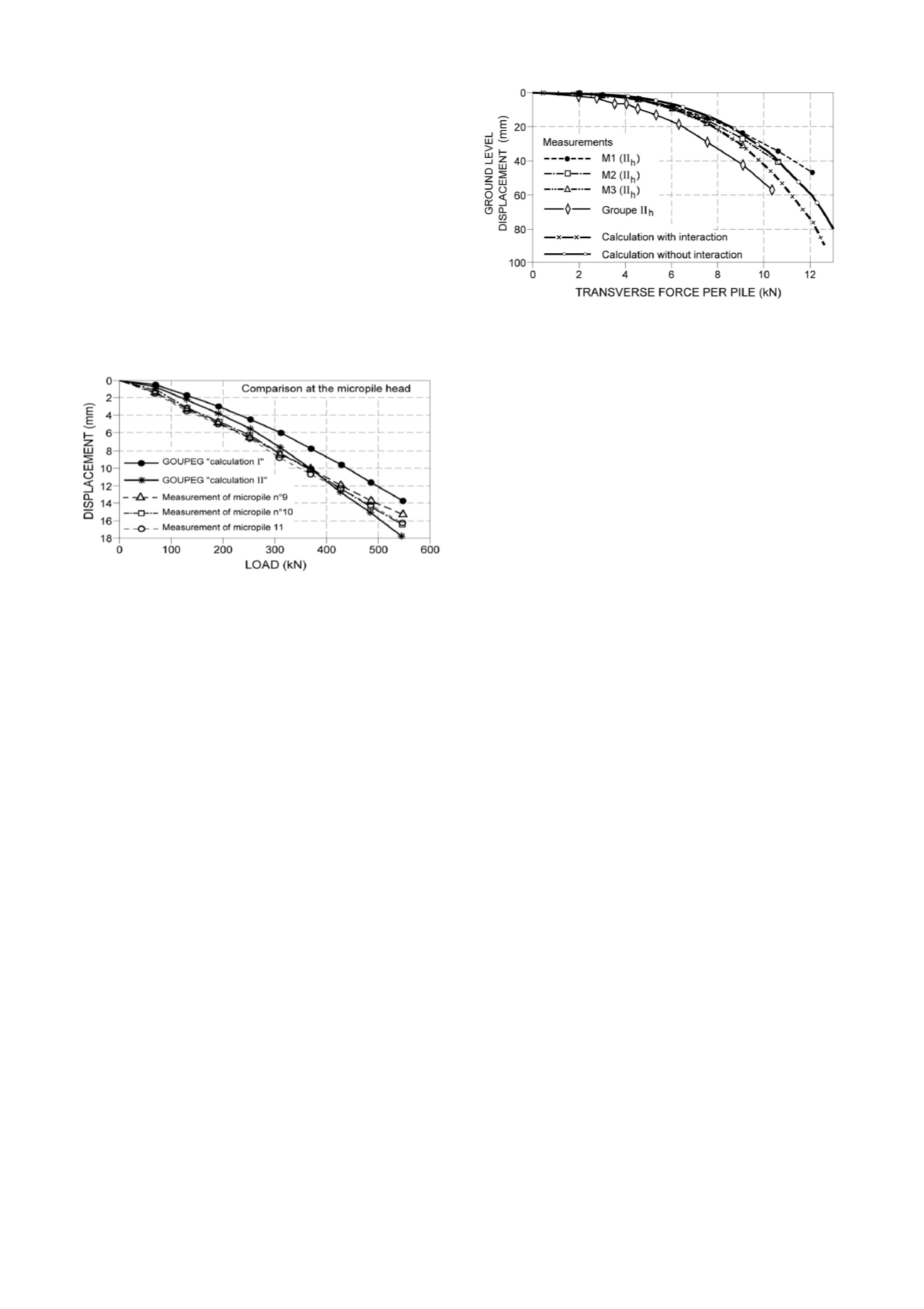
5.3.3 Analysis of the St Rémy transverse loading test
The GOUPEG Program was then extended to include an analysis
of micropile groups subjected to transverse loading, once again
in relying on Mindlin's equations. This analysis led to examining
both the vertical and horizontal loadings of full-scale tests
conducted in the sand at the CEBTP's St Rémy experimental
site, which included both isolated micropiles and two groups of
4 micropiles with the following parameters: S/B = 2; D = 5 m; B
= 10 cm; and I
D
= 0.57. The data required for this analysis were
the "
t-z
" curve of skin friction, the "
q-z
" curve of pile tip strength
and the "
p-y
" curve of transverse strength, with all these curves
being exclusively derived from on-site pressuremeter tests. To
calculate the group effect (i.e. the pile-soil-pile interaction), the
soil shear modulus G (input into Mindlin's equations) needed to
be evaluated. Figure 8 shows the comparison of experimental
results with GOUPEG calculations for the type II micropile
group (with gravity grouting). It can be observed that the
pressuremeter method developed for piles is also valid for
micropiles and moreover that for a given micropile group, the
trend yielded by GOUPEG represents reality quite well.
Fig. 8: Comparison of the force-displacement curves both measured and
calculated by GOUPEG, in the horizontal loading of
a type II micropile group (St Rémy test)
5.4
Networks of vertically-loaded micropiles
Experimental research on micropile networks, in which all
micropiles are inclined and vertical loadings have been
introduced, is uncommon. The large number of tests conducted
during
FOREVER
on vertically-loaded networks in sand have
made it possible to analyze the influence of the following
parameters: micropile spacing, sand density, and micropile
density and interlocking.
Within a network, micropile orientation is characterized by
two angles: angle
of micropile inclination with respect to the
vertical, and angle
, the so-called interlocking angle, between
the vertical plane containing the micropile and the vertical plane
tangent to a horizontal circle centered at the middle of the
foundation and passing by the micropile top. An interlocking
network is characterized by negative
values (
< 0° or > 180°),
which enables the micropiles to be spaced at smaller distances
than at the top, thus leading to greater soil confinement between
micropiles.
The initial experimental results were obtained by Lizzi
(1978), who used a 1/10 reduced-scale model to compare the
behavior of a group to that of a network, with each containing 18
micropiles. The improvement offered could be quantified either
by the coefficient of efficiency C
e
= 1.68, which indicates the
ratio of the load-bearing capacity of the group to that of all
isolated micropiles, or else by Ce = 2.22, i.e. the ratio of the
load-bearing capacity of the network to the sum of the load-
bearing capacities of all isolated vertical micropiles.
The
FOREVER
NP performed a series of 20 tests on
micropile networks in sand (full-scale, centrifuge, tank,
calibration chamber) by means of varying the parameter values.
The initial result was a wide dispersion in values of the Ce
coefficient (from 0.51 to 2.93), which can be explained in part
by the micropile installation mode: driving, boring, cast-in-place.
The relative S/B spacing does not appear to be a main parameter.
Sand density could hardly be studied since for all tests, the
density index I
D
of the sand was in the vicinity of 0.5, which
corresponds to a relatively loose sand. Regarding micropile
density or number N, it would appear that a minimum number of
micropiles per unit volume is required to generate a positive
group effect. As for micropile orientation and the values of
angles
and
, it also remained impossible to determine a
precise effect since too few tests actually allowed varying one of
these two parameters while keeping all other parameters
constant. It could nonetheless be confirmed that inclining an
isolated micropile hinders its vertical load-bearing capacity,
when compared to the load-bearing capacity of the same
micropile placed in a vertical position. On simple networks
composed of easels (A-shaped) however, results showed that a
mechanism specific to inclined micropiles developed during
vertical loading, involving the gradual mobilization of a passive
pressure with bending on the micropiles. This phenomenon,
Volume 6 - Page 81