


 84 / 479

Proceedings of the 18
th
International Conference on Soil Mechanics and Geotechnical Engineering, Paris 2013, volume 6, 2016
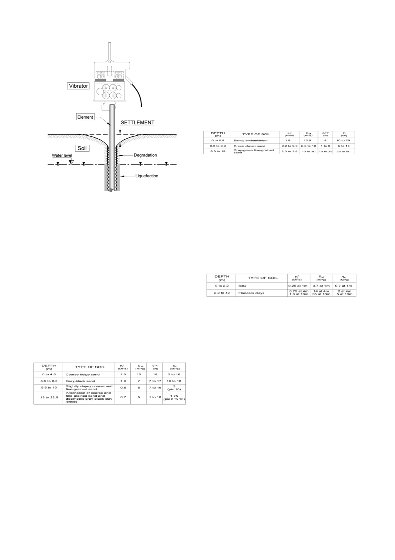
Fig. 10: Vibratory pile driving: Schematic diagram (Holeyman, 2002)
This work was wrapped up in 2006 by the publication of a
Vibratory Pile Driving Technical Guide, simultaneously in
French and English, distributed to attendees of the "
2006
Transvib
" International Symposium, held in September 2006 in
Paris, and widely disseminated since then.
6.2
Program framework
The studies and research conducted during this
Vibrofonçage
NP
contained three segments, each one composed of several phases:
-
Segment 1:
survey of practices, summary of previous
research projects, and preparation of Segment 2 (including
in
situ
testing and experiments);
-
Segment 2:
Execution of instrumented
in situ
vibratory pile
driving and pile loading tests, plus calibration chamber tests in
the laboratory;
-
Segment 3:
Analysis and interpretation of experimental
results, development of a computation code for vibratory pile
driving predictions (BRAXUUS software), issuance of a
technical guide, results presentation (organization of the 2006
Transvib Symposium).
Table 3: Geotechnical characteristics - Montoir site
Segment 2 experiments were held across four sites:
The Montoir tests were conducted in August 2001. A series
of full-scale tests took place at the time of expanding the freight
and container terminal at the Montoir Port (Nantes-Saint Nazaire
Port Authority).
The ground cross-sections and their geotechnical
characteristics are summarized in Table 3 above.
Two metal tubes closed at the 339-mm diameter, 14-mm
thick (length: 32 m) and instrumented at several levels (stress
gauges, accelerometers) were driven by vibration. One pile was
over-driven in order to evaluate its load-bearing capacity by a
dynamic test. A static loading test was then performed on the
other pile, for comparison with the results of a static loading test
on a driven pile of the same type at the same site in 1999.
The
Dunkirk
tests conducted in January 2002 involved three
tubes open at the base of a structure under construction and
driven by vibration; these tubes were fitted at the top with strain
gauges and accelerometers (a pile-driving control device
developed by TNO). Measurements recorded just at the top did
not give rise to any detailed interpretation.
The
Le Havre
tests were carried out in December 2002 at a
site made available by the Le Havre Port Authority in the zone
around the petrochemical facility adjacent to the Normandy
Bridge.
The ground cross-sections and geotechnical characteristics
are summarized in Table 4 below:
Table 4: Geotechnical characteristics - Le Havre site
A PU16 sheet pile (length: 14 m) and a probe (length: 14.5
m) used during a pervious experiment (i.e. a SIPDIS probe) were
installed. The probe had been instrumented on three levels, while
the sheet pile was fitted at both the top and tip, with one tube at
the top and tip and the other only at the top. Particle velocity
measurements at the soil surface were recorded during
installation of the two tubes and probe.
The
Merville
tests were undertaken from March to June 2003
at the Merville Airfield experimental site, under the supervision
of the LCPC. They were intended to measure, for comparative
purposes, the behavior of hammered and driven piles by means
of vibration into Flanders clay soils.
Their ground cross-sections and geotechnical characteristics
are summarized in Table 5 below:
Table 5: Geotechnical characteristics - Merville site
Two open tubes (length: 12.3 m) 508 mm in diameter, plus
two pairs of AU16 sheet piles (length: 13 m), were installed
under experimental site conditions. For each type of element,
one was driven by vibration using an ICE 815 vibrodriver while
the other was hammered to the same depth with an IHC S70
hammer. The elements were instrumented at both the top and tip.
The hold-down force, penetrating pile length, pressure and flow
rate of the hydraulic unit for this vibratory pile-driving test, the
hammer energy for hammering, and particle velocities at the soil
surface for distances of 5, 10 and 15 meters from the element
were all measured continuously during the pile penetration. Each
element was then subjected to an instrumented static loading test
in order to compare the load-bearing capacities obtained for each
of the two installation modes.
As a complement, physical modeling tests of the pile-driving
process by means of vibration were conducted inside the
CERMES calibration chamber at the ENPC Laboratory in
Marne-la-Vallée. A prototype vibratory pile-driving probe was
developed for penetration into a sand block reconstituted in the
chamber thanks to a hydraulic servo-cylinder. The probe, with a
10-cm
2
cross-section (i.e. the penetrometer standard), had been
instrumented to measure the pile cap strength as well as local
friction on a special sleeve. Moreover, the probe was fitted with
a tapered accelerometer. The parametric study completed by
relying on controlled force and controlled displacement tests
clearly exposed the influence of basic parameters (average static
force, amplitude and frequency of the cyclic force) on process
performance. These tests have given rise to a physical model that
may be simulated by running certain software, in particular the
BRAXUUS application developed during this NP.
Volume 6 - Page 84