


 78 / 479

Proceedings of the 18
th
International Conference on Soil Mechanics and Geotechnical Engineering, Paris 2013, volume 6, 2016
4.2.1 Wall No. 1 in a nailed soil stressed until failure
This 7-m high wall installed in sand was built by completing a 1-
m high excavation phase with sealed nails 6-8 m long, in
offering some bending strength due to its tubular composition.
The structure had been calculated using a sufficiently small
overall safety coefficient (F=1.1), capable of easily causing
breaking as the soil gradually saturated from the top of the wall,
thus reducing the sand's apparent cohesion while increasing its
total specific gravity. Thanks to the extensive instrumentation
installed, it was possible to perform a large number of
measurements (tension in the nails, facing displacement, strain in
the nailed soil mass, etc.). Moreover, since the failure was not
complete, given that the facing had penetrated and become
blocked in the foundation soil, excavating the wall allowed for a
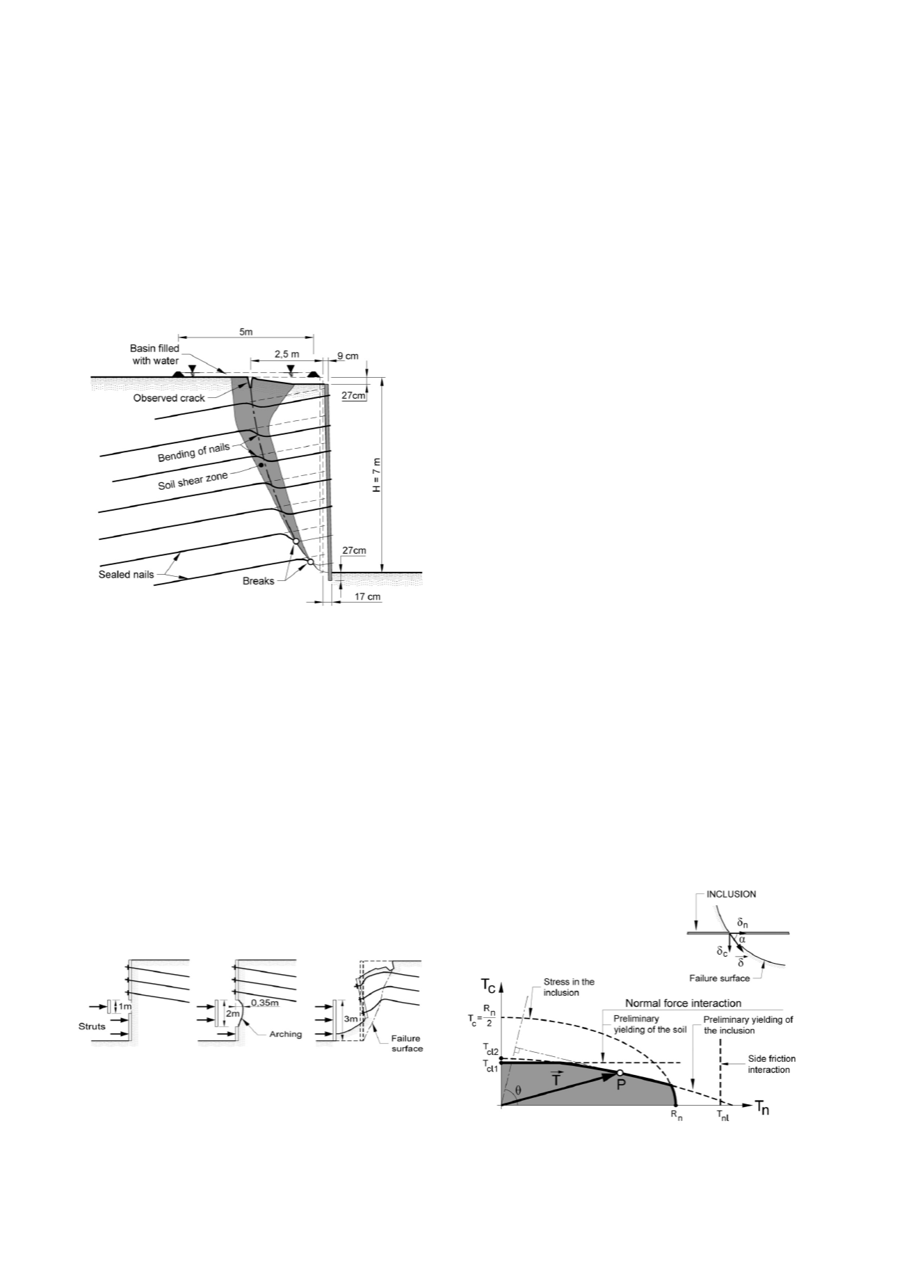
comprehensive investigation of the failed wall (Fig. 3).
Fig. 3: Observations recorded during excavation of the nailed soil wall
after failure (1
st
full-scale experiment held at the CEBTP site)
More specifically, nail bending in the vicinity of failure
creates a shear zone in the soil around the line of maximum
tension points in the nails; as a general rule, it also yields a non-
abrupt, and rather ductile, wall failure appearance.
4.2.2 Nailed soil wall N°2 under study during the excavation
phase
The objective of this experimental wall No. 2 tested at CEBTP
was to study the stability, both local and global, of a nailed soil
mass during an excavation phase. For this purpose, a nailed soil
wall 3 m high was first built and then stressed until failure by
increasing the excavation height from 1 to 3 m at the wall base.
During the first stage (i.e. 1-m excavation height), both the
excavation and wall were stable. For the second stage (2-m
excavation height), a localized failure ensued followed by
stabilization through the formation of an arch, yet overall the
wall remained stable. Lastly, for the third stage (3-m height), the
arching collapsed and local failure propagated all the way to the
surface, resulting in a global and internal wall failure.
Fig. 4: Stability and failure during the excavation phase of
the CEBTP's nailed soil Wall No. 2
4.2.3 Wall No. 3 in nailed soil - failure caused by insufficient
nail length
The third experiment at the CEBTP site on a nailed soil wall,
this one 6 m high, served to examine the failure mode due to
insufficient reinforcement length. This wall was equipped with
adjustable length telescopic nails. Failure occurred once a
distribution of very short nails had been reached along the base
of the wall with gradually increasing nail length towards the
upper part of the wall. This configuration dictated the shape of
the sliding surface, which corresponded to an intermediate
failure somewhere between an adherence deficiency mode and
an external failure mode.
4.3
Primary results from Clouterre I
Wall No. 1 revealed the shape of the maximum tension line in
the nails, i.e. remaining constant until the initiation of failure,
which is gradual, along with a certain trend towards nail bending
in the vicinity of failure.
Wall No. 2 indicated that wall stability during its construction
had been correlated with the development of an arching effect
over the course of excavation phases, which provided
information on process limitations among other things.
Soil/nail friction has been the topic of in-depth studies
involving both experimental and theoretical findings, with, like
in the Reinforced Earth technique, the notion of an apparent
friction coefficient
* correlated with a partially impeded
dilatancy of the granular part of the soil skeleton.
A major portion of the research was devoted to developing an
ultimate limit state (ULS) design method. The preference was
assigned to a failure method that makes use of circular failure
surfaces, calibrated with the full-scale wall No. 1. More
specifically, a so-called multicriteria method was developed
(Schlosser, 1982) to enable determining the torsor (T
n
, T
c
, M) of
forces at the point of maximum tension in a nail. This method
relies on a set of failure criteria focusing on components and the
interactions between components, namely:
- soil/nail skin friction interaction:
q
s
- soil/nail transverse pressure interaction: p
p
max
- nail constituent material:
k (max shear)
This work has led to identifying 4 criteria, in acknowledging
the assimilation of nails to beams, thus giving rise in the (Tn, Tc)
plane of tensile and shear forces to a domain of stability that
helps determine the maximum resultant force (Fig. 5).
These multiple criteria allow for a shear force in the nails that
often gets neglected when designing nailed soil walls, yet that
becomes a predominant concern when vertical nailing is used to
stabilize slopes. This design method was the first in the field of
soil mechanics to use a semi-probabilistic calculation with
partial safety coefficients and weighting coefficients on actions.
It has now become the rule in the Eurocodes.
Fig. 5: Domain of stability in the (T
n
, T
c
) plane,
and determination of maximum force T
Volume 6 - Page 78