1837
Technical Committee 205 /
Comité technique 205
following section. The creep criterion is selected to represent a
ULS anchor resistance.
The UK currently excludes Section 8 of EC7 from use in
that country in its National Annex and requires anchors to be
designed to BS8081 ‘Ground Anchorages’. The design of
anchors in that standard is based on the ‘working load’,
T
w
,
which is defined as ‘The safe load of the anchorage’. No
guidance is given in the standard as to whether
T
w
is determined
using a ULS calculation or using characteristic values, however
the terminology would suggest that it was originally considered
to be similar to
F
Serv;k
. In practice, it is considered that for
embedded walls,
T
w
is taken as the higher of that obtained using
either a limit equilibrium or a bending moment and
displacement analysis using appropriate pressure distributions.
The proof load is related to
T
w
, as discussed in the following
section, with different creep criteria to be satisfied which can be
related to a SLS and to a ULS resistance.
Section 8 has not been specifically excluded in Ireland,
nevertheless the practice is generally to adopt the BS8081
testing criteria with
T
w
based on a calculation using
characteristic actions and parameters. However, given the
general lack of specific guidance in this area prior to the
publication of the amended Section 8, some designers also
considered the value of
F
ULS,d
in the selection of
T
w
if that gave
a greater value.
Denmark uses the present EC7, section 8.
The anchor force
is based on a ULS design force found from a calculation of the
anchored structure with factored soil parameters. Some Danish
designers compute a service load (
F
Serv;k
),which considers
prestress/lockoff of the anchor. This force is such as to resist a
ULS if
F
Serv;k
is greater than
F
ULS;d
. This means that
E
ULS;d
=
F
Serv;k
if
F
Serv;k
> F
ULS;d
. The Proof load is then based on
E
ULS;d
and must satisfy a limiting creep criterion. Previously Denmark
used the German test method as described in DIN 4125.
However, with the introduction of EN 1537:1999 Denmark has
accommodated the incomplete test specifications stated in the
informative annex E of EN 1537:1999. Test method 1 (TM1) is
preferred because of the relationship to the former DIN 4125,
but the creep rate limit measured in the acceptance test using
TM1 in EN1537:1999 is so strict (0,8 mm), that often Test
Method 3 (TM3) is adopted because of the more moderate creep
rate limit (1,2 mm). Temporary anchors may be loaded to a
lower proof load than permanent anchors, provided the
consequence of failure justifies that. Similarly the effect of high
or serious consequences of failure are governed by the
reliability class concept as described in EC0, Annex B by
introducing a
K
FI
factor applied to the partial safety factor on
the load or on the resistance.
4 TESTING OF ANCHORS
Load testing of anchors has historically been an intrinsic part of
the design and execution of anchors – in particular grouted
ground anchors - and the mandatory acceptance testing of all
grouted anchors is required in EN 1997-1:2004/prA1:2012 and
in EN 1537:1999. The anchors are loaded to a proof load (
P
p
)
to verify limit state design requirements. The tests are
categorised as:
1. Investigation Tests undertaken to establish the geotechnical
ultimate resistance,
R
ULS;m
, of the anchor at the grout/ground
interface and to determine the characteristics of the anchor
within the working load range.
2. Suitability tests – carried out on site on anchors identical to
those to be used in the works – to investigate some
characteristics of the anchor and how the anchor performs under
working conditions.
3. Acceptance tests – carried out on every anchor installed in
the permanent works – to ensure that each anchor will perform
as designed.
For Investigation and Suitability tests
P
p
is derived from:
P
p
≥ ξ
ULS
x
γ
a;ULS
x E
ULS;d
(8)
For Acceptance tests
P
p
is derived from
E
ULS;d
or
F
Serv;k
;
P
p
≥ γ
a;acc;ULS
x E
ULS;d
(9)
or
P
p
≥ γ
a;acc;SLS
x F
Serv;k
(10)
The method is to be stated in the National Annex of each
country.
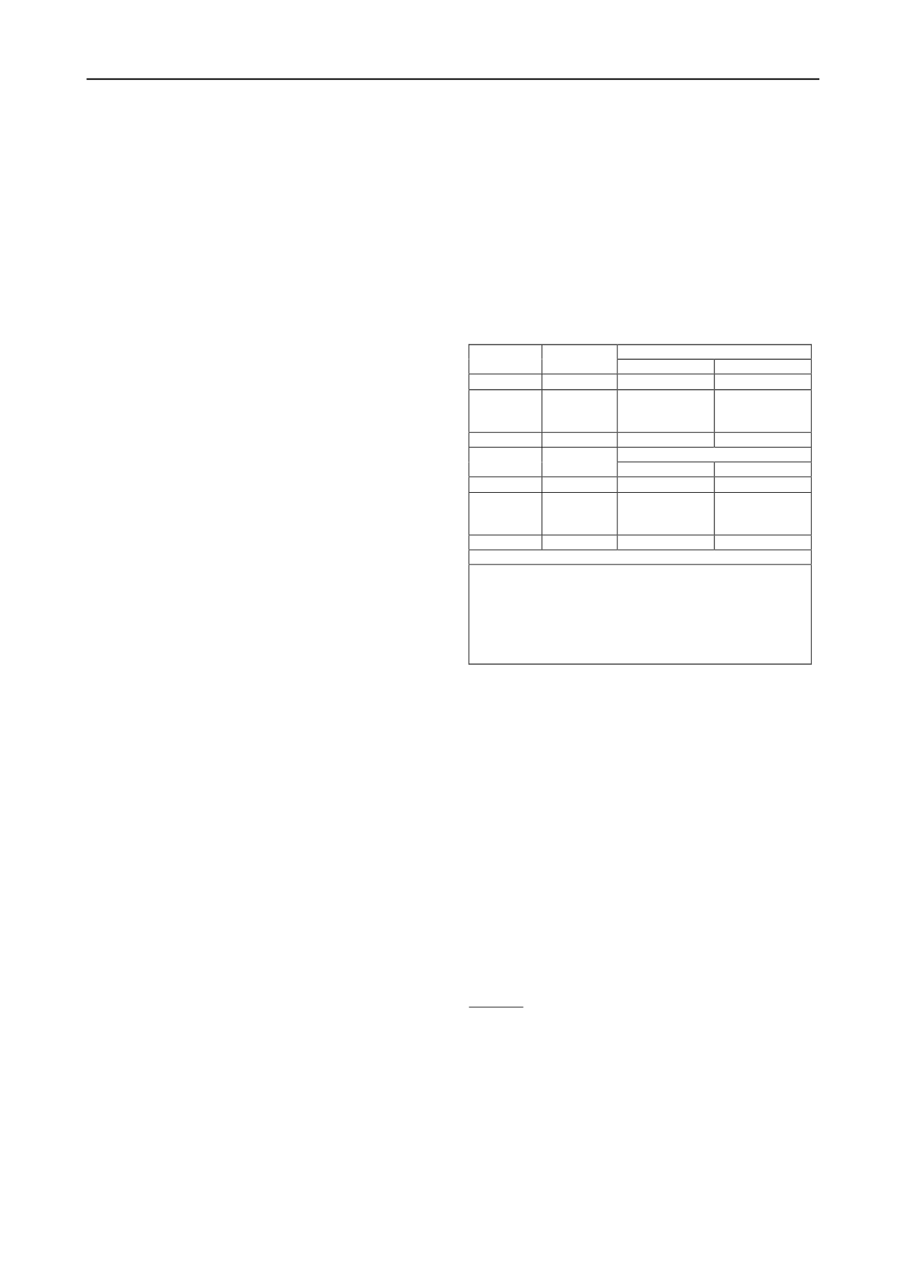
Table 1 - Limiting Criteria for investigation, suitability and acceptance
tests for persistent and transient design situations at the ultimate and
serviceability limit states (from EN 1997-1:2004/prA1:2012)
Test
Method
a
Limiting
criterion
Investigation and Suitability tests
ULS
SLS
1
α
1
2 mm
0.01
∆
e
b
2
k
l
(per log
cycle of
time)
2%
2%
3
α
3
5 mm
NA (use P
c
)
Test
Method
a
Limiting
criterion
Acceptance tests
ULS
SLS
1
α
1
2 mm
0.01
∆
e
2
k
l
(per log
cycle of
time)
2%
2%
3
α
3
NA
1.5 mm
c
Note: NA = Not applicable
a
Test methods are in accordance withDraft EN ISO 22477-5
Geotechnical investigation and testing - Testing of
geotechnical structures - Part 5: Testing of anchorages
b
∆
e
= (F
serv.k
x tendon free length)/(area of tendon x elastic
modulus of tendon)
c
Value given is for permanent anchors; for temporary
anchors,
α
3
= 1.8 mm
EN 1537:1999 provides for three methods to undertake the
suite of tests, essentially following the traditions in testing
developed and maintained in Germany, the UK and France. As
stated in section 3, these test methods are referred to as Test
Method 1, 2 and 3. This approach and test designation has been
implemented in EN 1997-1:2004/prA1:2012 and Draft EN ISO
22477-5 expected to be published in 2013.
The provisional limiting criteria for ULS and SLS resistance
for these tests to EN 1997-1:2004/prA1:2012 are given in Table
1. The methods of execution and interpretation of the tests are
to be found in Draft EN ISO 22477-5. This standard makes no
specific reference to testing for either SLS or ULS stating that
proof loads are to be set in accordance with EN1997-1. Not all
countries have the requirement to determine the limiting criteria
for SLS of the anchor as this is considered to be satisfied if the
test results meet the ULS criteria.
The test methods currently adopted in Germany, Denmark,
France, Ireland and the UK are summarised below. It should be
noted that some countries already use partial factors whilst
others still adopt a more global safety factor approach.
Germany.
1. Follow Test Method 1
2.
For all categories of test (investigation, suitability and
acceptance), proof load is:
P
p
=1,1 x 1,35 x F
Serv;k
(11)
or
P
p
=1.1 x F
ULS;d
(12)
3. Limiting criteria based on value of
α
1
for
investigation, suitability and acceptance tests.
Acceptance tests are required to satisfy the
α
1
criterion, but the test is shorter than that required for
suitability tests.


