 
          902
        
        
          Proceedings of the 18
        
        
          th
        
        
          International Conference on Soil Mechanics and Geotechnical Engineering, Paris 2013
        
        
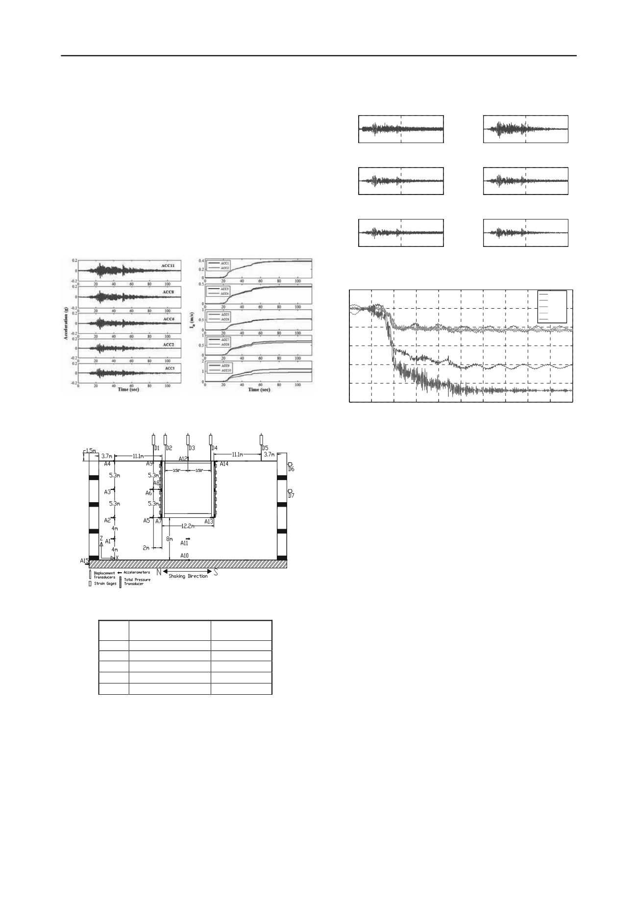
          records at the same elevation on the structure and in the free-
        
        
          field during the Izmit event, showing an amplification of
        
        
          movement near on the roof of the structure.
        
        
          Figure 10 presents the recorded settlements at various
        
        
          locations with respect to the structure, showing larger
        
        
          settlements in the free-field, which decreased towards the
        
        
          structure. This settlement pattern was expected due to the
        
        
          smaller weight of the tunnel compared to the adjacent soil. A
        
        
          larger settlement of the surrounding soil compared to the tunnel
        
        
          led to an overall decrease in permanent lateral earth pressures
        
        
          on the walls after each shaking event. These results are
        
        
          currently being studied in combination with strain distributions
        
        
          and direct pressure measurements for different underground
        
        
          structures and base motions for Test 1 and the subsequent tests.
        
        
          (a)
        
        
          (b)
        
        
          Figure 7: Measured acceleration recordings in the free-field test
        
        
          compared in the middle and near the container boundary.
        
        
          Figure 8. Instrumentation layout in Test-1 (prototype scale)
        
        
          Table 3. Achieved Motions in Test-1
        
        
          No.
        
        
          Ground Motion
        
        
          Achieved
        
        
          PGA
        
        
          1
        
        
          Izmit - Istanbul
        
        
          0.3
        
        
          2 Northridge - Sylmar
        
        
          0.3
        
        
          3 Northridge - Sylmar
        
        
          0.8
        
        
          4 Northridge - Sylmar
        
        
          1.1
        
        
          5
        
        
          Loma - LGPC
        
        
          1.0
        
        
          5 CONCLUSIO
        
        
          ynamic centrifuge
        
        
          were co ted on scalse-
        
        
          crete water reservoirs currently
        
        
          uthern California. The goal of testing was
        
        
          N
        
        
          D
        
        
          m
        
        
          experiments
        
        
          nduc
        
        
          odel buried reinforced con
        
        
          being designed in so
        
        
          to verify 2-D and 3-D numerical models of equivalent
        
        
          underground structures restrained at the top and bottom. The
        
        
          data from these experiments will help evaluate the effects of
        
        
          seismic soil-structure-interaction (SSI) on the distribution of
        
        
          accelerations and lateral earth pressures on underground
        
        
          structures with different stiffnesses, soil conditions, and input
        
        
          ground motion characteristics. This paper includes a discussion
        
        
          of the centrifuge testing plan for evaluating the seismic response
        
        
          of buried structures, including the container characterization,
        
        
          development of scale model structures, instrumentation
        
        
          challenges and preliminary results.
        
        
          0
        
        
          50
        
        
          100
        
        
          -0.5
        
        
          0
        
        
          0.5
        
        
          ACC7


          max = -0.22
        
        
          0
        
        
          50
        
        
          100
        
        
          -0.5
        
        
          0
        
        
          0.5
        
        
          ACC 2


          max = -0.23
        
        
          0
        
        
          50
        
        
          100
        
        
          -0.5
        
        
          0
        
        
          0.5
        
        
          ACC8
        
        
          time (s)


          max = -0.25
        
        
          0
        
        
          50
        
        
          100
        
        
          -0.5
        
        
          0
        
        
          0.5
        
        
          ACC 3


          max = -0.22
        
        
          0
        
        
          50
        
        
          100
        
        
          -0.5
        
        
          0
        
        
          0.5
        
        
          ACC9


          max = -0.34
        
        
          0
        
        
          50
        
        
          100
        
        
          -0.5
        
        
          0
        
        
          0.5
        
        
          ACC 4


          max = -0.27
        
        
          Time (s)                                                   Time (s)
        
        
          Figure 9. Acceleration time histories (in prototype “g”) recorded in the
        
        
          free-field and on the structure during the Izmit event in Test-1.
        
        
          0
        
        
          10
        
        
          20
        
        
          30
        
        
          40
        
        
          50
        
        
          60
        
        
          70
        
        
          80
        
        
          90
        
        
          100
        
        
          -10
        
        
          -8
        
        
          -6
        
        
          -4
        
        
          -2
        
        
          2
        
        
          0
        
        
          Time (s)
        
        
          Settlement (cm)
        
        
          LVDT 1
        
        
          LVDT2
        
        
          LVDT3
        
        
          LVDT4
        
        
          LVDT5
        
        
          Figure 10. Settlement recorded at various locations with respect to the
        
        
          structure in Test-1 during the Izmit event.
        
        
          6 ACKNOWLEDGEMENTS
        
        
          The authors w
        
        
          epartment of
        
        
          Water and Power for the financial support of this project and the
        
        
          versity of Colorado Boulder.
        
        
          l
        
        
          g,”


            15


            th


            World Conf. on EQ Eng


          ., Lisbon.
        
        
          Divis, C.J., Kutter, B.L., Idriss, I.M., Goto, Y., and Matsuda, T.
        
        
          G
        
        
          Zurich, Switzerland.
        
        
          ould like to thank the Los Angeles D
        
        
          centrifuge facility staff at the Uni
        
        
          7 REFERENCES
        
        
          Dashti, S., Gillis, K., Ghayoomi, M., and Hashash, Y. (2012).
        
        
          “Sensing of Lateral Seismic Earth Pressures in Geotechnica
        
        
          Centrifuge Modelin
        
        
          (1996). “Uniformity of Specimen and Response of Liquefiable
        
        
          Sand Model in Large Centrifuge Shaker,”


            6


            th


            Japan-US


            Workshop on Earthquake Resistant Design of Lifeline


            Facilities and Countermeasures against Soil Liq


          . pp. 259-274.
        
        
          hayoomi, M., Dashti, S., McCartney, J.S. (2012a).
        
        
          “Performance of a Transparent, Flexible Shear Beam-Type
        
        
          Container in Dynamic Centrifuge Modeling of Geotechnical
        
        
          Systems,”


            J. of Soil Dyn. and EQ Eng.


          (under review).
        
        
          Ghayoomi, M., Dashti, S., McCartney, J.S. (2012b). “Effect of
        
        
          Boundary Conditions on the Performance of a Transparent
        
        
          Flexible Shear Beam-Type Container,”


            2


            nd


            Int. Conf. on Perf.-


            Based Design EQ Geotech. Eng.


          , Taormina, Italy.
        
        
          Palmer, M.C., O’Rourke, T.D., Olson, N.A., Abdoun, T., Ha,
        
        
          D., O’Rourke, M.J. (2009). “Tactile Pressure Sensors for Soil-
        
        
          Structure Interaction Assessment.”


            J. of Geotech. and Geotech.


            Eng.,


          ASCE, 1638-1645
        
        
          Mason, H.B., Bray, J.D., Kutter, B.L., Wilson, D.W., and Choy,
        
        
          B.Y. (2010). “Earthquake motion selection and calibration for
        
        
          use in a geotechnical centrifuge.”


            7th Int. Conf. on Physical


            Modeling in Geotechnics


          .