892
Proceedings of the 18
th
International Conference on Soil Mechanics and Geotechnical Engineering, Paris 2013
electroosmosis. In this equation,
V
m
is the maximum voltage
applied to the soil and
T
v
is the time factor, which depends on
the distance
L
between the electrodes and on the time
t
, and is
given by Equation 4.
v
n
n
w
h
me
w
h
e
TA B sen
A
k
Vk xV
k
k u
2
0
2
exp
)1(
2 )(
(3)
with
2
2
1
n A
and
L
x n
B
2
1
2
L
tc T
v
v
(4)
According to Mitchell and Soga (2005), the solution of
Equation 3 is given by Equation 5 (parameter A given in Eq. 3)
(Mitchell and Soga 2005), where
U
is the average degree of
consolidation. These authors present some abacus with the
solution for several cases.
(5)
v
n
n
TA
A
U
2
0
2
exp )1(
4 1
In case of radial flow occurring simultaneously, Equation 2
can be converted into Equation 6, where
r
is the distance
measured in the horizontal direction,
c
r
is the coefficient of
consolidation in this direction,
x
here is measured along the
vertical direction, as well as
c
v
, and the other parameters were
already explained. Mitchell and Soga (2005) also found the
solution for this equation. The case voltage V=0V can also be
found by solving this equation, by correcting radius
r
to
consider each drain.
t
u
x
u c
r
V
k
k
r
u
r r
V
k
k
r
u c
v
w
h
e
w
h
e
r
2
2
2
2
2
2
2
2
1
(6)
3 SOIL, EQUIPMENT AND TESTS PERFORMED
The material used in the tests is a commercial white Kaolin
(w
L
=75%, IP=40%, classified as CH). Reconstituted specimens
were prepared with water content equal to 1.5 w
L
and were
normally consolidated for a maximum stress of 12 kPa. The
electrical resistivity of the saturated soil for different water
contents (and therefore void ratios) was also measured in order
to confirm that this parameter does not changes significantly
during the performance of the oedometer tests. Further details
can be found in Nogueira Santos (2012).
Some calibration tests were performed first to ensure that the
oedometer equipment was isolated from the electrical system.
This motivated the adoption of a PVC ring instead of a stainless
steel ring, because PVC is an electrical insulator material.
A commercial 9V battery cell was adopted to apply the
electrical flow to the soil. Later, a modified mobile phone
battery charger was used, which is shown in Figure 1. This
source has a DC voltage of 6.39V and an intensity of 0.71A and
was chosen because the batteries were not able to keep constant
voltage for long periods of time.
Figure 1. Modified mobile phone battery charger
Two different types of tests were performed where several
different cases were tested. The specimens of the first type were
tested in a normal oedometer cell adapted to apply an electrical
field to the soil. Tests were performed with and without the
application of electrical DC voltage and two different voltages
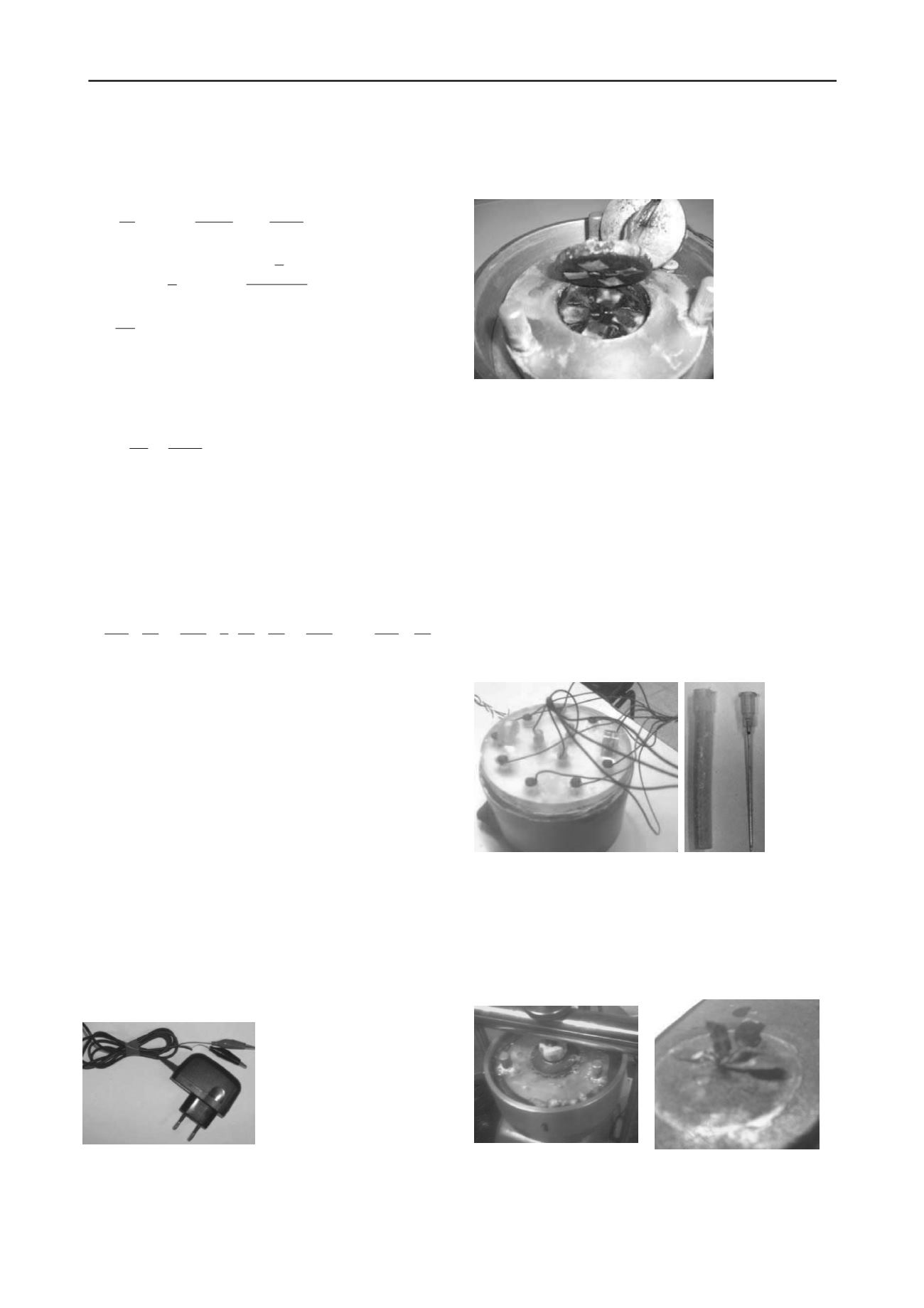
were tested: 6.35V and 9V. The oedometric cell used was
modified to include four silver electrodes (square plates) in the
top and in the bottom porous stones, as shown in Figure 2.
Figure 2. Silver electrodes on the porous stone
For the second type of tests a new consolidation cell was
developed to include vertical drains. The spacing of the drains
was designed so that radial flow would occur instead of vertical
flow. This cell (120mm diameter and 70mm high) is made of
acrylic and is shown in Figure 3. The top load plate of the cell
was drilled to allow the inclusion of the drains and the
settlement of the soil without interference. A geosynthetic
material was placed between the specimen and the load plate to
enable drainage from the top. The drains introduced allowed
drainage by hydraulic gradients generated by the increment of
vertical stress, or drainage generated by this mechanical action
as well as with the application of an electrical field. The radius
for the volume of soil surrounding each drain is 14mm, which
allows considering that drainage occurs mainly in the radial
direction. For the last case, medical needles were used as
electrodes, placed inside the drains. The drains considered are
the needles cases filled with fine sand shown in Figure3.
Figure 3. Apparatus for the radial flow test and detail of the drains.
Electrodes corrosion and the formation of an oxide were
detected during the electroosmotic one-dimensional tests, as
well as the formation of gas bubbles. Figure 4 shows some
photographs of the gas formation (a) and the electrode corrosion
(b). The silver oxide produced in test EO3 is shown in Figure 5.
Only electrodes corrosion was observed in the electroosmotic
radial flow tests.
(a)
(b)
Figure 4 – (a) Gas formation (b) Electrode Corrosion.


