2122
Proceedings of the 18
th
International Conference on Soil Mechanics and Geotechnical Engineering, Paris 2013
Nº/Type of Anc.
L
fix
T
ult
τ
ault
f
eff
m
kN
kN/m
2
8 SBMA (18 units) 2.5
450–540
322-386
1
2 Conventional
7.5
960-1080
230-254
0.59-0.79
3.4
Summary
An extensive series of field anchor tests performed in different
soils showed that:
-
there is no direct proportionality between fixed anchor
length and its ultimate load capacity;
-
obtained values of the average ultimate bond stresses
in cohesive soils fit well with Ostermayer´s (1974)
diagrammatic presentation of skin friction against fixed
length, while results obtained in gravelly sands fit well
with Ostermayers and Scheele (1978) presentation of
ultimate load capacity vs. anchor length;
-
ranges of obtained efficiency factors are consistent
with tendency of values proposed by Barley (1995);
-
efficiency factor can be considered as a conceptual
control of anchor ultimate capacity;
-
fixed anchor lengths longer than 10 m do not
contribute significant beneficial effects on capacity.
-
SBMA anchors permits construction of high anchor
capacities that approach more than two times that of
the conventional anchors which utilize long inefficient
fixed length.
4
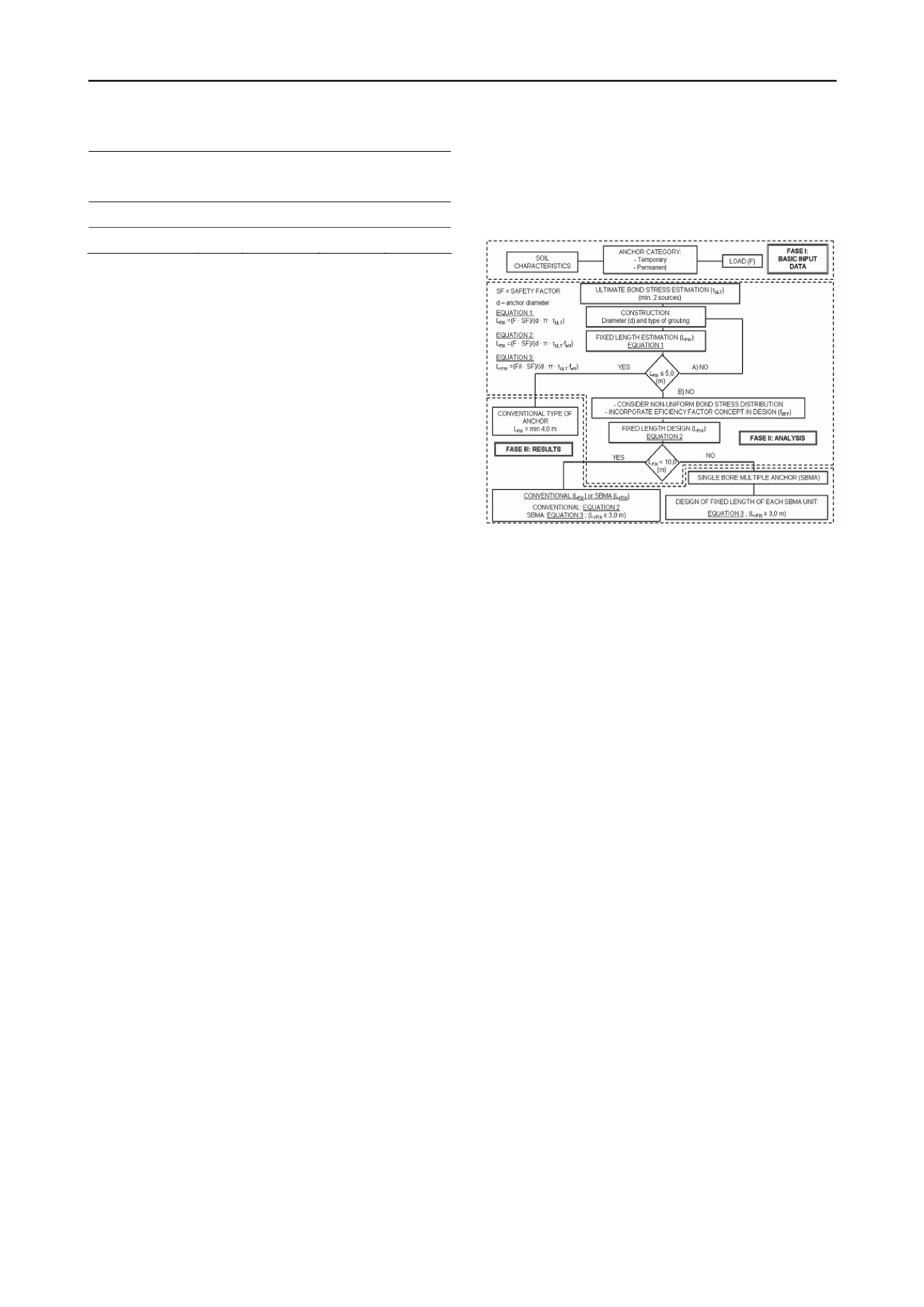
PROPOSAL FOR DESIGN METHODOLOGY
Based on the information presented in previous chapters,
proposal for design methodology for cement grouted anchors
formed by steel tendons is presented below, considering most
important parameters that define its capacity, like: soil
characteristics, execution process, ultimate and average bond
capacity, fixed length, type of anchors (conventional or SBMA),
stress distribution and efficiency factor.
Emphasis is placed on the effects of progressive debonding
that cause the non-uniform stress distribution along the fixed
length, with efficiency factor as a conceptual control of anchor
capacity. Due to the number of parameters that enter the
analysis, recommended methodology has an iterative character,
as it can be seen in Figure 6. Some of the most important steps
of the flow chart are commented below.
Phase I: Evaluation of the site subsoil conditions and
relevant properties of in situ soil and rock, as a factor that
directly influence steps in the Phase II (construction system and
skin friction estimation).
Phase II: For the skin friction estimation it is recommended
to use at least two sources, taking into account the concept or
formula that will be applied for the anchor design. If pre-design
load tests are performed to evaluate ultimate anchor load
capacity, construction process has to be exactly the same as
planned for production anchors, and fixed lengths should be
similar with test anchors.For the first iteration anchor length is
calculated considering uniform bond stress distribution
(Equation 1). If calculated fixed length is larger than 5 m,
construction process can be reconsidered (Alternative A),
varying anchor diameter or type of grouting, with objective to
reduce fixed length up to 5 m. Other option (Alternative B) is to
introduce directly the efficiency factor.
Phase III: If the fixed length obtained considering non-
uniformity is in the range between 5 and 10 m, two alternatives
are proposed. First alternative considers conventional type of
anchor, with unique fixed length unit calculated taking into
account efficiency factor (f
eff
) – Equation 2. Another alternative
is the application of SBMA. In this case fixed length of each
unit that forms SBMA is calculated considering corresponding
efficiency factor (f
eff
) – Equation 3.
If the fixed length, obtained considering non-uniformity is
greater than 10 m it is recommended to apply SBMA anchors.
Figure 6. Flow chart for design of fixed anchor length.
5
REFERENCES
Barley A.D. (1995). Theory and Practice of the Single Bore Multiple
Anchor
System. Proc. Int. Symposium Salzburg.
Balkema
Rotterdam, pp 293-301.
Barley A.D. (1997). The Single Bore Multiple Anchor System.
Proc.
Int. Conf.: Ground anchorages and anchored structures
. London,
pp. 65-75.
Barley A.D. and Windsor, C.R. (2000). Recent advances in ground
anchor and grout reinforcement technology with reference to the
development of the art.
GeoEng 2000, Int. Conf. on Geotechnical
and Geological Engineering
. Melbourne, pp. 1083-1094.
Berardi G. (1967). Sul Comportamento Deglic Ancoraggi Immersi in
Terreni Diversi.
Universidad Genoa, Inst. Contr. Sc. Serie
III (60),
pp 18-19.
Briaud J.L., Powers W.F. and Weatherby D.E. (1998). Should Grouted
Anchors Have Short Tendon Bond Length?.
Journal of Getechnical
and Geoenvironmental Engineering ASCE
, pp. 110-119.
BrS 8081 (1989). British Standard Code of Practice for Ground
Anchorages. BSI, London.
Casanovas (1989). Anchoring in rock. Elsevier Scientific Publishing
Company, pp 0-33.
Coates D.F. and Yu Y.S. (1970). Three dimensional stress distribution
around a cylindrical hole and anchor.
Proc. of 2 Int. Conf. on Rock
Mechanics
. Belgrade, pp. 175-182.
EN 1537 European Standrad (2010). Execution of special geotechnical
work – Ground Anchors.
Mesci J. (1997). Some Practical and Theoretical Aspects of Grouted
Soil Anchors.
Proc. of Int. Conf. Ground Anchorages and
Anchorages Structures
. London, pp. 119-130.
Muller H. (1966). Erfhnungenmit Verakurungen System BBRV in Fels-
und Lock-ergensteinen.
Schweisezerische Bauzeitung
, 84 (4), pp.
77-82.
Ostermayer H. (1974). Construction carrying behavior and creep
characterics of ground anchors.
Int. Conf. On Diaphragm Walls and
Anchorages. I.C.E.
London, Septiembre 18-20, pp. 141-151.
Ostermayer H. and Scheele F. (1977). Research and Ground Anchors in
Non-Cohesive Soils.
Géotechnique
3, pp. 92-97.
Weerasinghe R.B. (1993). The Behaviour of Anchorages in Weak
Mudstone. PhD Tesis, University of Bradford.
Woods R.I. and Barkhordari K. (1997). The Influence of Bond Stress
Distribution on Ground Anchor Design.
Proc. of Int. Conf. Ground
Anchorages and Anchorages Structures
. London, pp. 55-64.


