2665
Technical Committee 212 /
Comité technique 212
resulted in a portion of the load to be transmitted through the
contact at the raft-soil interface.
Table 2. The parameters used in the FEA.
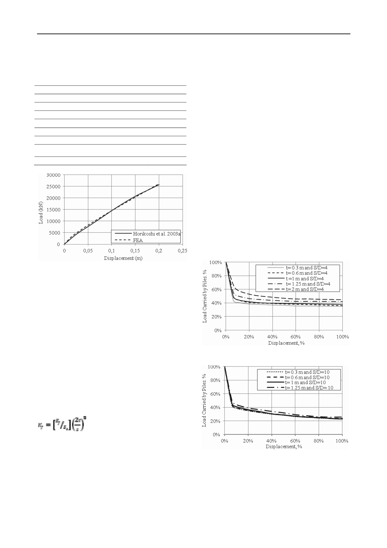
Figure 3. Comparison of the FEA and centrifuge test results.
3 EFFECT OF PILED RAFT PARAMETERS ON ITS
LOAD SHARING SCHEME
In a piled raft, different factors affect the load sharing between
the raft and piles but with varying influence on the load sharing.
The raft flexibility, which is governed by its thickness and the
spacing between the piles, affects the load sharing between the
raft and piles, and will be investigated. For example, increasing
the raft width is expected to increase the load transmitted by the
raft. On the other hand, increasing the pile diameter is expected
to increase the load transmitted through the piles. The effects of
these two parameters are examined and the results obtained are
discussed in this section. The load carried by the piles will be
presented as a percentage of the total vertical load applied on
the raft.
3.1
Effect of raft thickness
Brown (1969) evaluated the foundation flexibility using finite
element analysis. He proposed a relationship between the
thickness of the raft and its flexibility, given by:
(2)
Where E
f
= Young's modulus for raft; E
s
= average soil elastic
modulus; t= raft thickness; and s= spacing between piles.
Thin or flexible rafts tend to deform more than rigid or thick
rafts. This increased deformation of a flexible raft establishes
intimate contact with the subsoil, resulting in increased load
carried by the raft. Equation 2 may be used for the assessment
of the flexibility of a piled raft, but considering the spacing
between the piles instead of the raft width, B. Using the spacing
between piles is appropriate in representing the flexibility of the
piled raft as small pile spacing results in a s smaller deformation
at the raft center in comparison with large spacing. Considering
Eq. 2, the raft can be characterized according to the following
conditions: (i) perfectly rigid if K
f
> 10; (ii) perfectly flexible
when K
f
< 0.01; and (iii) intermediate flexibility at K
f
varies
between 0.01 to 10 (Mayne and Poulos 1999). The load sharing
scheme for piled rafts with varying flexibility is investigated.
Figures 4 and 5 show the load carried by the piles for two
different pile spacing with various raft thicknesses as a function
of the piled raft total displacement.
At initial small displacement, most of the load is carried by the
piles; this is believed to be due to the lack intimate contact
between the raft and subsoil. Similar behavior was reported by
Horikoshi and Randolph (1996). As the displacement increases,
the proportion of the load carried by the piles dropped
significantly at about 7% of the total displacement and
continued to decrease gradually after that. At about 80% of
displacement, the load transmitted by the piles reached a plateau
and became almost constant. The variation in load carried by
the pile is noticeable at S/D=4; the load carried by the piles is
about 35% and 45% for raft thickness, t= 0.3 m and t= 2 m,
respectively. The raft flexibility, K
f
= 0.2 and 8.73 for these two
cases. On the other hand, K
f
= 0.29 and 0.02 if the spacing is
S/D=10 for the same raft thickness values. Due to the narrow
range of K
f
for the large spacing case, the variation in
percentage of load carried by the piles is insignificant, and it is
approximately 25%. This is attributed to the large pile spacing,
which renders even the thick raft flexible, resulting in increased
raft soil interaction, compared to the case of the raft with small
pile spacing. Poulos (2001) reported a similar percentage of
25% of the load carried by the piles.
Figure 4. Load carried by piles with different raft thicknesses and
S/D=4.
Figure 5. Load carried by piles piles with different raft thicknesses and
S/D=10.
3.2
Effect of raft size
The raft width contributes to the bearing capacity of the raft. As
the raft width increases, the contact area with the subsoil
increases and hence the load carried by the raft increases. The
load carried by the piles was evaluated for different raft widths
varying from 4 m to 7 m with the same pile diameter (0.5m),
spacing ratio (4D) and raft thickness (1.25 m) (i.e. relatively
Soil
Concrete
Constitutive Modeling
Mohr-Coulomb
Linear Elastic
Unit Weight (kN/m
3
)
14.6
23.6
Angle of internal friction
45
-
Modulus of Elasticity
4500 kN/m
2
23.6 GN/m
2
Poisson’s ratio
0.175
0.21
Stiffness increases with depth
Yes
No
Incremental Modulus of
Elasticity (kN/m
2
/m)
6500
-
Interface reduction factor
0.43
-


