2664
Proceedings of the 18
th
International Conference on Soil Mechanics and Geotechnical Engineering, Paris 2013
This paper investigates the performance of piled raft
foundations and their load sharing mechanism employing a 3D
finite element model calibrated/verified using geotechnical
centrifuge data.
2 DEVELOPMENT OF FINITE ELEMENT MODEL
The development of the FEM in this study consisted of
three main steps. First, a 3D FEM was established to simulate
the behavior of piled raft foundation considering an appropriate
size mesh and number of elements. Second, the results of a
centrifuge study of piled raft performed by others were used to
calibrate the FEM created in this study. Lastly, the calibrated
FEM was employed to perform a parametric study to evaluate
the effect of different parameters on the overall performance of
piled raft foundation.
0
40
80
120
160
200
0
5
10
15
20
25
Depth (mm)
Cone Tip Resistance, q
c
(MN/m
2
)
2.1
Description of FEM
A finite element model (FEM) was developed using the
Plaxis 3D software package (Plaxis bv. 2011). A quarter of the
piled raft foundation system was modeled taking advantages of
symmetry across the x and y-axes to reduce the computation
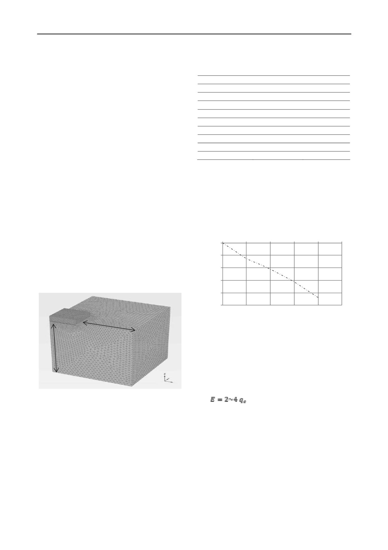
effort and time. The boundaries of the model were set at a
distance equal to 1.5B~2B (where B is raft width) measured
from the edge of the raft, and the depth of the model was
approximately two times the pile length as shown in Figure 1.
The model was built using about 275,000 3D 10-node
tetrahedral elements. The average size of the element was
approximately 110 mm. The large number of small size
elements assured high accuracy of the results at locations where
non-linear behavior is anticipated (e.g. raft base, pile base and
pile circumference). The load was applied using uniform
prescribed displacement applied at the top of the raft, and the
corresponding load was evaluated.
Figure 1. The FEM used in the current study.
2.2
Centrifuge testing used to calibrate FEM
Horikoshi et al. (2002, 2003a, b) employed geotechnical
centrifuge testing in order to simulate the complicated soil-
structure interaction problem for a piled raft under different
types of loading. The results of the vertical loading case from
their studies will be considered herein to calibrate the 3D finite
element model. The tests were conducted under 50g centrifugal
acceleration. The model consisted of four piles rigidly
connected to the raft. The raft and piles models were made of
aluminum. Toyoura sand was used as the model ground
(Horikoshi et al. 2003a). Table 1 summarizes the dimensions of
the model in both model and prototype scales.
Table 1. The dimensions of the model in both model and prototype
scales.
Model
Prototype (n=50)
Diameter (mm)
10
500
Wall thickness (mm)
1
Solid
Materials
Aluminum
Concrete
Pile length
170 mm
8.5 m
Modulus of Elasticity
71 GPa
41.7 GPa
Raft thickness
40 mm
2.0 m
Raft width (square)
80 mm
4 m
Pile Spacing
40 mm
2 m
Number of piles
4
4
Cone penetration tests (CPT) were performed in-flight to
evaluate the sand strength using a miniature cone penetrometer.
The cone tip resistance profile is shown in Figure 2. It is noted
that the strength (and stiffness) increased with depth, which is
expected for sand soil. This strength profile will be simulated in
the FEM through the input parameters such as the initial
modulus of elasticity and the incremental modulus of elasticity,
which will account for the increase in stiffness with depth.
1.5B~2B
Figure 2. In-flight results for CPT (after Horikoshi et al. (2003a).
2.3
Calibration of FEM
The behavior of the Toyoura sand was simulated using a
linear elastic-perfectly plastic Mohr-Coulomb constitutive
model. Matsumoto et al. (2004b) reported that the peak friction
angle,
, for Toyoura sand is about 45
and the reduction factor,
R
int
, at the interaction surface between the pile and Toyoura
sand is 0.43 (Horikoshi et al., 2003a). The modulus of elasticity
was correlated to the cone tip resistance, q
c
, using the
relationship proposed by Tomlinson (1996), i.e.
2L
p
(1)
All input parameters used in the FEM are listed in Table 2.
The process of calibration was performed by refining the soil
and interface properties in the FEM. This was done by adjusting
the values of the interface reduction factor values at the pile-soil
interface; and the estimated initial modulus of elasticity and
incremental increase of modulus of elasticity with depth (i.e.
within the range stipulated in Eq. 1). After a number of trials,
the FEM a reasonable match with the centrifuge test results was
achieved as demonstrated in Figure 3.
The slight nonlinear behavior observed at relatively low
displacement is attributed to the movement of the pile caused by
slippage at pile-soil interface and increased strains at the pile
base, reaching plastic condition. This piles movement resulted
in more intimate contact between the raft and soil, which


