3524
Proceedings of the 18
th
International Conference on Soil Mechanics and Geotechnical Engineering, Paris 2013
Figure 6. Normalized equivalent
!
versus time for 35 acceleration
records from 14 earthquakes.
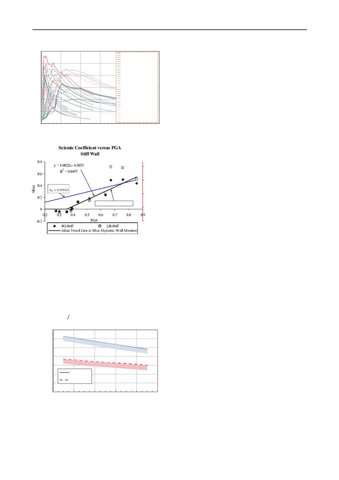
Figure 7. Back-calculated dynamic earth pressure coefficients at time of
maximum dynamic wall moments on stiff walls as function of peak
ground acceleration measured at the top of soil in free field (after Al
Atik and Sitar, 2009) with modification to relationship with
!
.
4
STATIC DESIGN VS. SEISMIC DESIGN
It is important to note that a wall designed for static lateral
forces usually includes a factor of safety of 1.5. The factor of
safety is then reduced to 1.1 for the occasional, temporary
forces due to earthquakes. Therefore, a statically designed
structure can withstand a seismic load of
!"#!$#%
= 1.5 1.1
!"#"$%
= 1.36
!"#"$%
(5)
Figure 8. Upper bound of PGA covered by static design versus internal
frictional angle
In other words, if the increment of seismic load is less than 36%
of the static load, the static design will be adequate for the
seismic condition. By introducing Equations (1) and (2), we can
obtain the upper boundaries of PGA that are covered by static
design as shown in Figure 8.
5
CONCLUSION AND RECOMMENDATIONS
While much research has been conducted on seismic earth
pressures in the last 80 years, various questions are still arising.
The author of this paper intended to have a more detailed
examination of the seismic earth pressures of restrained walls as
well as the seismic coefficient. Based on the results of serial
elasto-plastic finite element analyses and the examination of the
relationship between the seismic coefficient (
!
) and the peak
ground acceleration (PGA), it is concluded that the increment of
total seismic earth pressure acting on restrained walls be
calculated using the following equation:
∆
!!
= 0.3 ∙
∙
!
(6)
The thrust point of the total earth pressure (including static
and seismic) can be calculated from Equation (2). If the peak
ground acceleration is less than that graphed in Figure 8,
seismic design may not be necessary.
6
ACKNOWLEDGEMENTS
The author appreciates the support and help of Mr. Robert J.
Johnson, GE, and Mr. Allen D. Evans, GE, in the preparation of
this manuscript.
7
REFERENCES
ASSHTO (2010). “LRFD Bridge Design Specifications.” 5
th
Ed.,
Washington, D.C.
Al Atik, L. and Sitar, N. (2010). “Seismic Earth Pressures on Cantilever
Retaining Structures.” J. Geotech. Geoenviron. Eng., 136(10),
1324–1333.
Anderson, D. G., and et al. (2008). “Seismic analysis and design of
retaining walls, buried structures, slopes, and embankments.”
NCHRP Rep. 611, Transportation Research Board, Washington,
D.C.
Berg, R. R., et al. (2009). “Design and Construction of Mechanically
Stabilized Earth Walls and Reinforced Soil Slopes – Volume I”
FHWA-NHI-10-24, Washington, D.C.
FEMA (2003), “Recommended Provisions for Seismic Regulations for
New Buildings and Other Structures (FEMA 450).” 2003 edition.
Kramer, S. L. (1996). Geotechnical Earthquake Engineering, Prentice
Hall. Upper Saddle River, New Jersey; 1
st
ed., 653 pp.
Maleki1, S. and Mahjoubi, S. (2010). “A New Approach for Estimating
the Seismic Soil Pressure on Retaining Walls.” Transaction A:
Civil Engineering, Vol. 17, No. 4, pp. 273 - 284.
Mononobe, N., and Matsuo H. (1929). “On the determination of earth
pressures during earthquakes.”
Proceedings World Engineering
Congress
, Vol. 9.
Okabe, S., (1926). General theory of earth pressure.
Journal of the
Japan Society of Civil Engineers
, 12(1), Tokyo.
Ostadan, F. (2004). Seismic Soil Pressure for Building Walls-An
Updated Approach, 11
th
ICSDEE and 3
rd
ICEGE, University of
California, Berkeley.
Seed, H.B. and Whitman, R.V., (1970). “Design of Earth Retaining
Structures for Dynamic Loads.” ASCE Specialty Conference,
Lateral Stresses in the Ground and Design of Earth Retaining
Structures. Cornell University, Ithaca, NY., 103-147.
Veletsos, A. and Younan, A. (1994). ”Dynamic Modeling and Response
of Soil
-‐
Wall Systems.” J. Geotech. Engrg., 120(12), 2155–2179.
Whitman, R.V. (1991). “Seismic Design of Earth Retaining Structures.”
Proceedings, Second International Conference on Recent Advances
in Geotechnical Earthquake Engineering and Soil Dynamics, St.
Louis, MO, 1767-1778.
Wood, J. 1973. Earthquake-Induced Soil Pressures on Structures,
Report EERL 73-05, CalTech, Pasadena, California.
Wu, G. and Finn, W.D., 1999. “Seismic lateral pressures for design of
rigid walls.” Can. Geotech. J. 36: 509–522.
Yi, F. (2011). “Seismic Earth Pressures under Restrained Condition.”
ICTPA 24th Annual Conference & NACGEA International
Symposium on Geo-Trans, Los Angeles, California.
0
0.05
0.1
0.15
0.2
0.25
0.3
0
20
40
60
80
100
120
Normalized Equivalent k
H
ratio (k
H
/PGA)
Time (sec)
Tokachi-Oki (1968/5)Hachinohe (EW)
Tokachi-Oki (1968/5)Hachinohe (NS)
Miyagi-Oki (1978/6)OfunatoBochi (E41S)
Miyagi-Oki (1978/6)OfunatoBochi (N41E)
Northridge (1994/1)EW
Northridge (1994/1)NS
Athens (1999/9)Chalandri (EW)
Athens (1999/9)Gys (EW)
Athens (1999/9)Kede (EW)
Athens (1999/9)Chalandri (NS)
Athens (1999/9)Gys (NS)
Athens (1999/9)Kede (NS)
SanFernando (1971/2)CaltechAthenaeum (N00E)
SanFernando (1971/2)CaltechAthenaeum (S00W)
SanFernando (1971/2)CaltechMillikan (N00E)
SanFernando (1971/2)PacoimaDam (S16E)
SanFernando (1971/2)PalmdaleFirestation (S30W)
Helena (1935/10)CarrollCollege (S00W)
ElCentro ImperialValley (1934/12) (S00W)
ElCentro ImperialValley (1940/5) -S00W
ElCentroEarthquakeRecord (EW)
ElCentroEarthquakeRecord (NS)
GoldenGatePark (1957/3)SanFrancisco (N10E)
KernCounty (1952/7)CaltechAthanaeum (S00E)
KernCounty (1952/7)HollywoodStorageBasement (N90E)
KernCounty (1952/7)HollywoodStorage P.E.Lot (N90E)
KernCounty (1952/7)HollywoodStorage Penthouse
KernCounty (1952/7)TaftLincolnSchool (N21E)
Olympia (1949/4) WesternWa (N04W)
Olympia (1949/4) Seattle (S02W)
Parkfield (1966/6) Cholame-Shandon (N65E)
Parkfield (1966/6) Temblor#2 (N65W)
LongBeach (1933/3)Vernon (N82W)
k
H
= 0.47PGA - 0.1675
-0.09
0.01
0.11
0.21
0.31
-‐0.2
0
0.2
0.4
0.6
0.8
0.2
0.3
0.4
0.5
0.6
0.7
0.8
0.9
k
H
Proposed:
0
0.05
0.1
0.15
0.2
0.25
0.3
0.35
29
31
33
35
37
39
PGA Upper Bound (g)
Internal Frictional Angle (˚)
By sliding
By bending


