1794
Proceedings of the 18
th
International Conference on Soil Mechanics and Geotechnical Engineering, Paris 2013
SP1
SP2
SP3
SP4
SP5
SP6
SP7
2.5
2.5
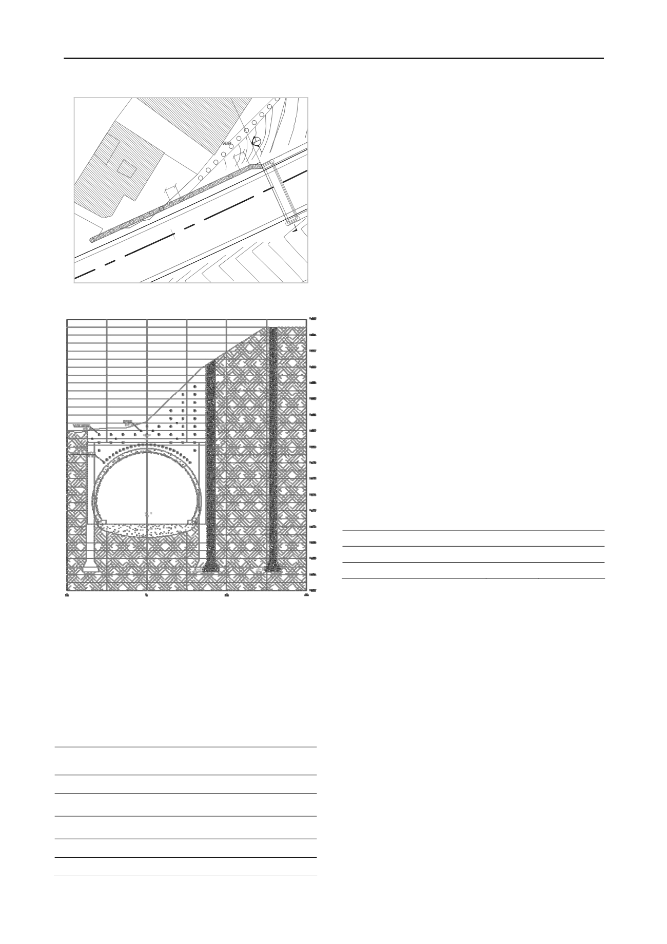
3+100
EAST
PORTAL
SP8
SP9
SP10
SP11
SP12
SP13
SP14
SP15
SP19
SP20
SP21
SP22
SP23
SP25
SP26
SP27
SP28
Figure 1. Plan of Niayesh east portal - north tunnel
Figure 2. Section A-A, (see Figure 1)
Based on the field and the laboratory test results, subsurface
conditions are described as follows:
Generally, filling material can be found to El. +1480 that is
about 2 meter above tunnel. Beneath the filling soil layer, soil
profile is composed of dense sandy gravels and dense clayey
gravels, both contains silt and clay material. Table 1 shows the
geotechnical properties of different soil materials.
Table 1.Geotechnical parameters of different layers
Elevation
To +1480
+1480 to
+1475
Under
+1475
Cohesion (kg/cm
2
)
0.1
0.2
0.3
Poisson Ratio ν
0.32
0.3
0.3
Frictional Angle (·)
35
35
35
Natural density (gr/cm
3
)
1.8
1.9
1.9
Young’s Modulus (kg/cm
2
)
600
650
650
3 NUMERICAL ANALYSES
3.1 Softwares
Numerical analyses have performed by 3D finite element
software released by Plaxis company. Plaxis3D Tunnel is a
finite element package specifically intended respectively for the
analysis of deformation and stability in tunnel projects.
The NATM construction progress were modelled by stepped
construction phases. In the applied performance method, after
excavation of each stages, a 15 cm reinforced shotcrete layer,
supported with lattice elements, will cover the excavated
surface as an initial lining. The well-known Hardening-Soil
model (Schanz et al. 1999) was used to model the soil layers.
3.2
Input parameters
Regarding 3 dimensional tools, Plaxis3D Tunnel can be used to
analyze some non-planar problems. Therefore, eastern portal of
the north tunnel is modelled by Plaxis3D Tunnel.
Construction stages are simulated in analyses and
geometry of slope and material parameters were considered
similar to analysis conditions described below.
The soil parameters assigned as presented in table 1. Soil
nails and forepoles are modelled by geogrid elements and initial
lining elements are modelled by plate elements. Geogrids are
with normal stiffness but no bending stiffness. They can only
sustain tensile force and no compression and plates are
structural elements with bending and axial stiffness. The most
important parameters of plates are flexural rigidity (bending
stiffness) EI and axial stiffness EA.
Character of all the plate elements used as a interior
temporary beam element which removed during the
construction stages applied as internal lattice that presented in
table 2 and characters of all of the plate elements used to model
initial lining of the tunnel, including 15 cm reinforced shotcrete
and steel lattices, applied as external lattice.
Table 2.Structural element properties
Element
EA (KN/m)
EI (KN.m
2
/m)
Internal lattice
5.3E6
1.4E4
External lattice
7.4E6
3.8E4
In this section, the results of the short-term stability and
performance analysis of the north tunnel under the reinforced
slop are presented. The model geometry was established
according to the project specifications. Considering the adjacent
buildings, the distributed load of 6000 kg/m2 is applied and
2000 kg/m2is applied for the highway that abuts under the slop.
At the location of the portal, the north tunnel will be
constructed in minimum depth of 7 m under toe of the
reinforced slop. Regarding the stages of the construction of the
tunnel, the staged construction applied in the numerical
modelling.
In staged construction right top and bottom drifts, as it is
shown in figure 3, are removed after left top and bottom drifts,
respectively. All the stages are followed by placing initial lining
elements on excavated soil face.
It should be noted that in the 3D model the portal is
excavated before tunnel construction.


